
Linear compressor

a compressor and linear technology, applied in the field of linear compressors, can solve the problems of affecting the efficiency of an associated refrigerator appliance, negatively affecting the operation of the linear compressor, and affecting the efficiency of the associated refrigerator applian

Active Publication Date: 2015-08-13
HAIER US APPLIANCE SOLUTIONS INC
View PDF79 Cites 25 Cited by
  • Summary
  • Abstract
  • Description
  • Claims
  • Application Information

AI Technical Summary

Benefits of technology

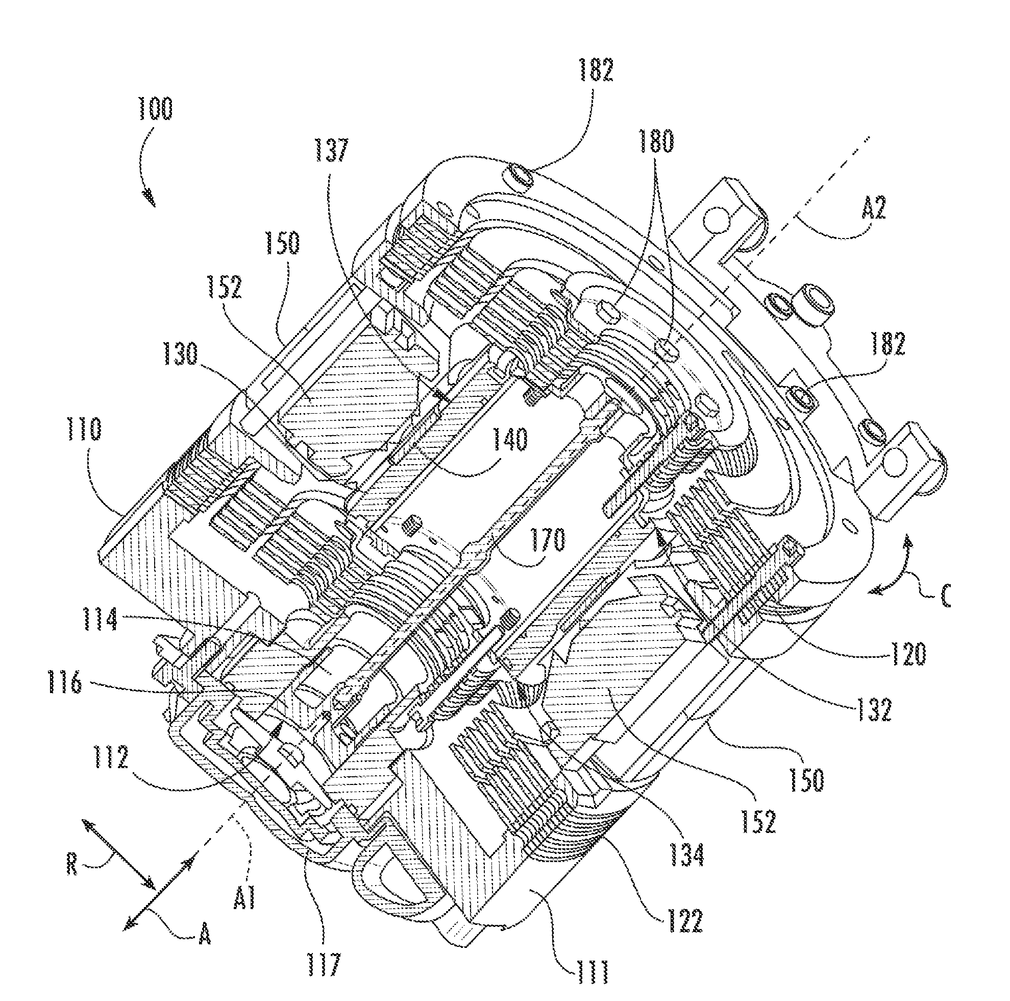
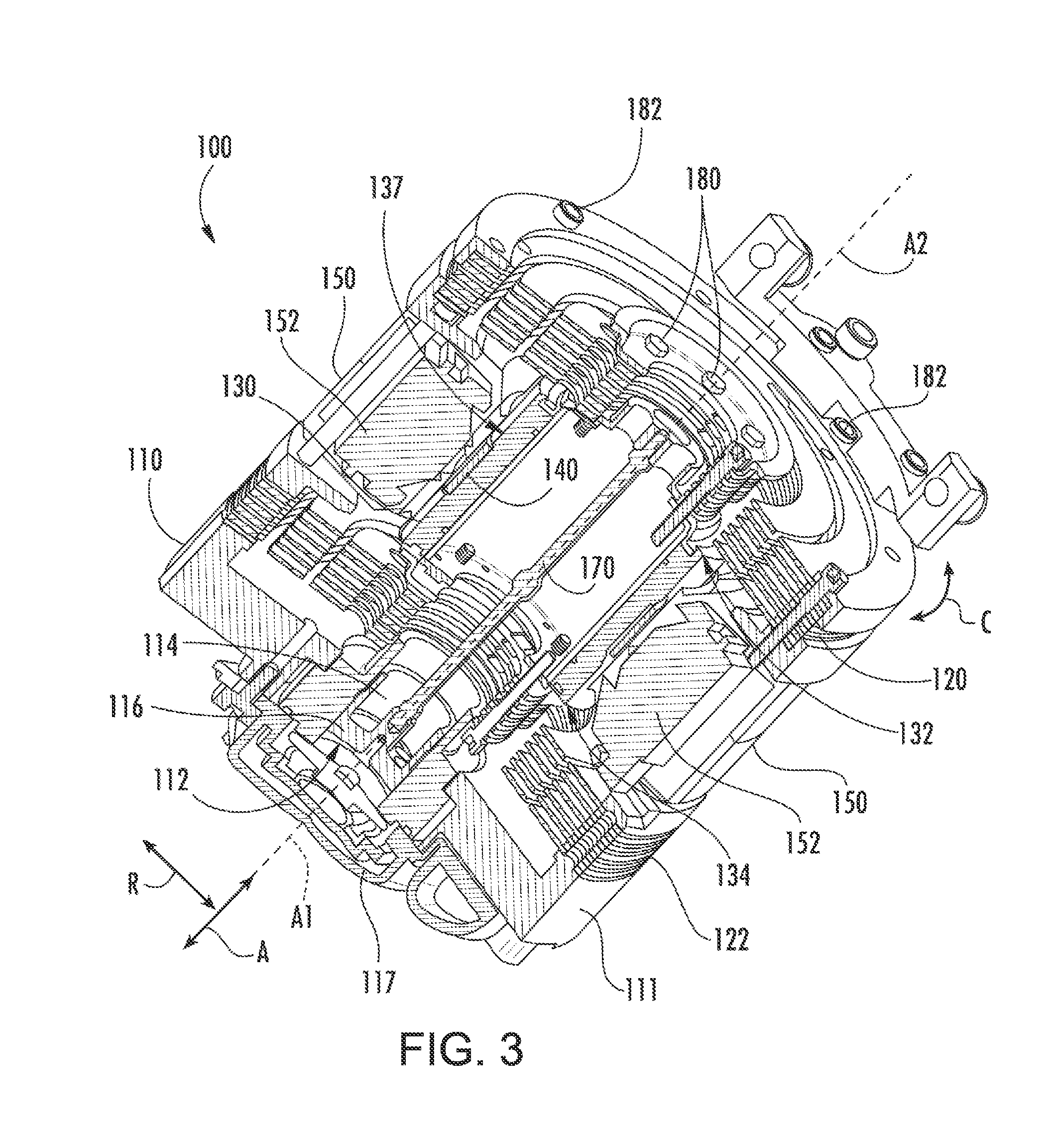
The present invention provides a linear compressor with a unique design. The compressor includes a cylinder assembly, a piston, and a driving coil. There are also two planar spring assemblies that are mounted to an inner back iron assembly, which extends along a first end and a second end. A magnet is mounted to the inner back iron assembly at the outer surface, facing the driving coil. The planar spring assemblies are positioned at the opposite ends of the inner back iron assembly. The compressor is designed to move the inner back iron assembly along a second axis during operation, making it suitable for use in a variety of applications. The technical effect is the improved performance and reliability of the linear compressor.

Problems solved by technology

However, friction between the piston and a wall of the chamber can negatively affect operation of the linear compressors if the piston is not suitably aligned within the chamber.
In particular, friction losses due to rubbing of the piston against the wall of the chamber can negatively affect an efficiency of an associated refrigerator appliance.
However, multiple air gaps can negatively affect operation of the linear compressor by interrupting transmission of a magnetic field from the driving coil.
In addition, maintaining a uniform air gap between the magnet and the driving coil and / or inner back iron can be difficult.

Method used


Image

  • Linear compressor
  • Linear compressor
  • Linear compressor

Examples


Embodiment Construction

[0030]Reference now will be made in detail to embodiments of the invention, one or more examples of which are illustrated in the drawings. Each example is provided by way of explanation of the invention, not limitation of the invention. In fact, it will be apparent to those skilled in the art that various modifications and variations can be made in the present invention without departing from the scope or spirit of the invention. For instance, features illustrated or described as part of one embodiment can be used with another embodiment to yield a still further embodiment. Thus, it is intended that the present invention covers such modifications and variations as come within the scope of the appended claims and their equivalents.

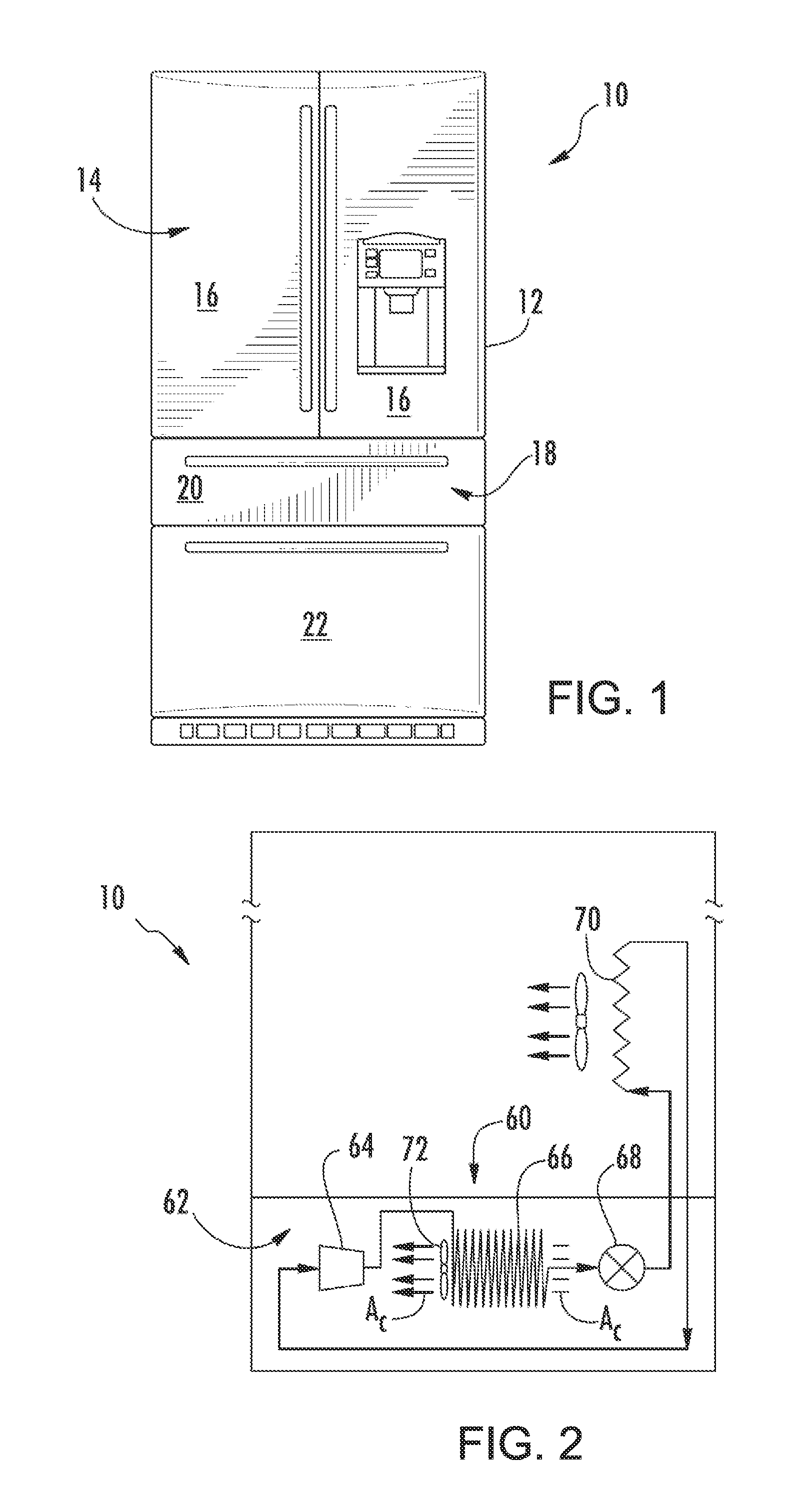
[0031]FIG. 1 depicts a refrigerator appliance 10 that incorporates a sealed refrigeration system 60 (FIG. 2). It should be appreciated that the term “ refrigerator appliance” is used in a generic sense herein to encompass any manner of refrigeration applian...


PUM


Abstract

A linear compressor is provided. The linear compressor includes a pair of planar spring assemblies mounted to an inner back iron assembly at opposite sides of the inner back iron assembly. A magnet is mounted to the inner back iron assembly at an outer surface of the back iron assembly.

Description

FIELD OF THE INVENTION[0001]The present subject matter relates generally to linear compressors, e.g., for refrigerator appliances.BACKGROUND OF THE INVENTION[0002]Certain refrigerator appliances include sealed systems for cooling chilled chambers of the refrigerator appliance. The sealed systems generally include a compressor that generates compressed refrigerant during operation of the sealed system. The compressed refrigerant flows to an evaporator where heat exchange between the chilled chambers and the refrigerant cools the chilled chambers and food items located therein.[0003]Recently, certain refrigerator appliances have included linear compressors for compressing refrigerant. Linear compressors generally include a piston and a driving coil. The driving coil receives a current that generates a force for sliding the piston forward and backward within a chamber. During motion of the piston within the chamber, the piston compresses refrigerant. However, friction between the pisto...

Claims


Application Information

Patent Timeline
Patent Type & Authority Applications(United States)
IPC IPC(8): F04B35/04
CPCF04B35/045F04B39/0005F04B39/122
Inventor HAHN, GREGORY WILLIAMBARITO, THOMAS R.
Owner HAIER US APPLIANCE SOLUTIONS INC
Features
  • Generate Ideas
  • Intellectual Property
  • Life Sciences
  • Materials
  • Tech Scout
  • Unparalleled Data Quality
  • Higher Quality Content
  • 60% Fewer Hallucinations
Learn More