Insulated Tube Joint Connection

Inactive Publication Date: 2015-08-13
NELSON GLOBAL PROD +1
View PDF10 Cites 18 Cited by
  • Summary
  • Abstract
  • Description
  • Claims
  • Application Information

AI Technical Summary

Benefits of technology

[0010]The present invention is related to a pipe connection that is insulated and yet provides strength, durability

Problems solved by technology

This arrangement is adequate for most of the tube, but tube end portions with clamp seats are not insulated because the clamps and clamp seats are attached to the ends of adjacent tube sections.
Such connectors are sturdy and effectively transfer loads from one tube section to another, but the location and size of the clamp seats and clamp make insulating the end portions of the tubes difficult, and result in a significant loss of heat at the connection even though most other portions of the tubes have exterior insulation.
Further, with an uninsulated joint, the clamp temperature can be very high when exhaust gase

Method used


Image

  • Insulated Tube Joint Connection
  • Insulated Tube Joint Connection
  • Insulated Tube Joint Connection

Examples


Embodiment Construction

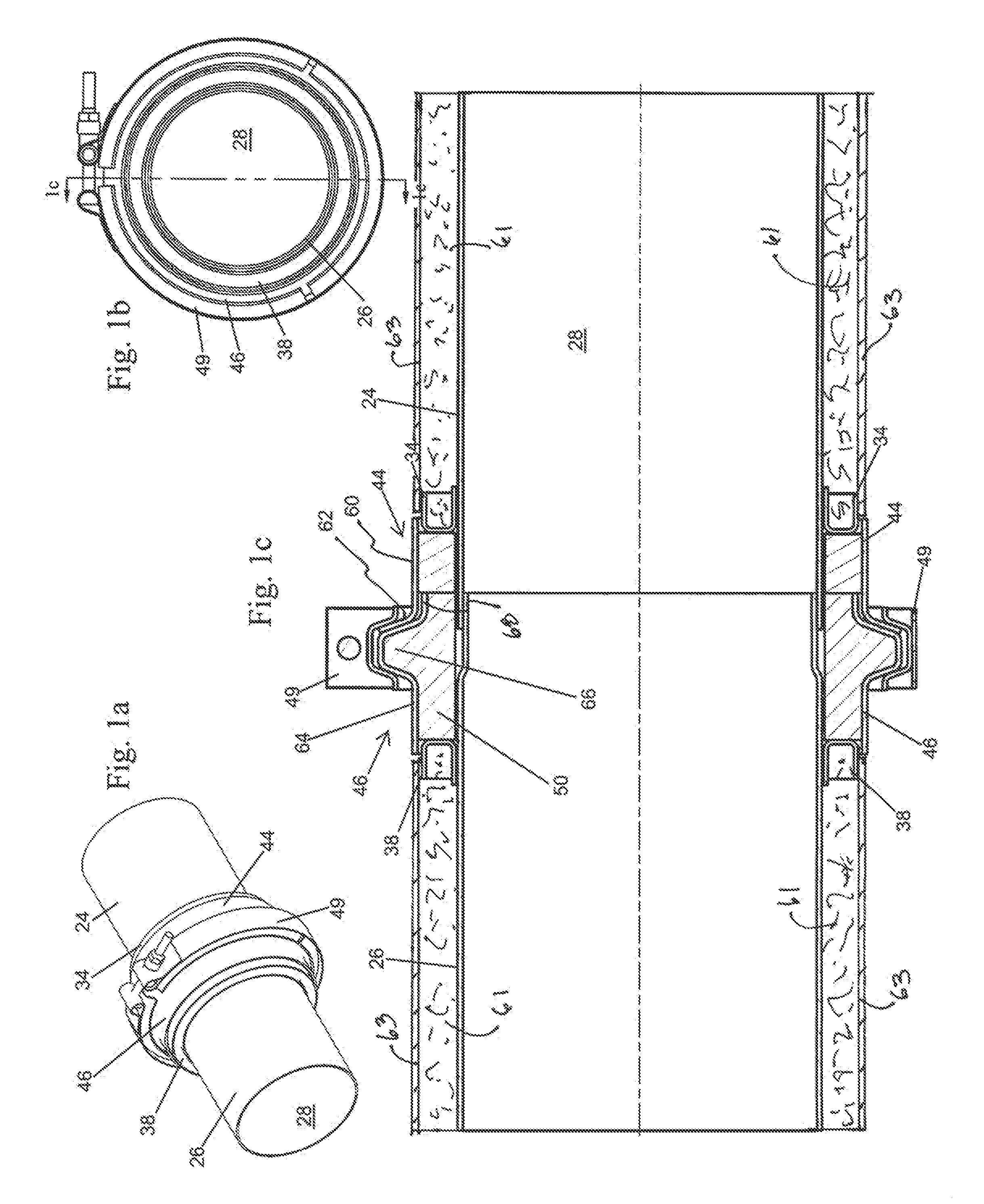
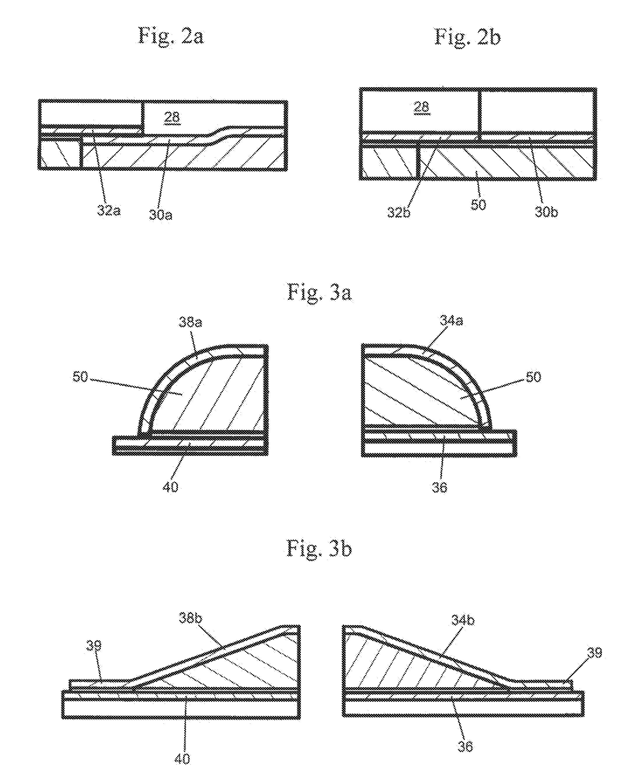
[0032]In the following detailed description of the invention, the same reference numerals will be used to identify the same or similar elements in each of the figures, unless otherwise noted.

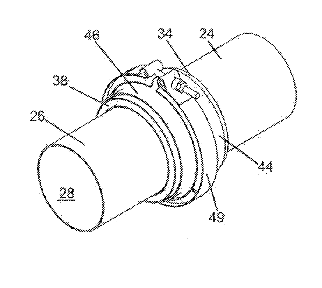
[0033]Illustrated generally in FIGS. 1a through 1c, and 4a through 4h is an insulated tube joint connection 20 including a first tube 24 and a second tube 26 that are joined together to define a conduit 28 through which relatively high temperature exhaust gases flow from an internal combustion engine to an exhaust aftertreatment device, heat exchangers, or other downstream elements. The engine and exhaust aftertreatment devices are not illustrated in detail, but either or both of the illustrated first tube 24 and the second tube 26 could be a part of or joined to an engine or exhaust aftertreatment device or they can be separate tube sections.

[0034]The terms “first” and “second” are used herein for ease of reference only and are not intended to be limited to upstream or downstream tubes and comp...


PUM


Abstract

An insulated tube joint connection having a tube with an end portion, a load transfer rim joined to and extending radially outwardly from the tube, and a clamping seat joined to the load transfer rim and spaced apart from the tube end portion to at least partially define an insulation space.

Description

FIELD AND BACKGROUND OF THE INVENTION[0001]This invention relates generally to tubes through which high temperature gases flow, and more particularly to an insulated tube joint connection.[0002]Vehicles of many types use tubes to transfer exhaust gases from an engine to mufflers or aftertreatment components such as catalytic converters, heat exchangers, or other downstream elements. Optimum treatment of the exhaust gases in the aftertreatment device can depend on the gases being at a relatively high gas temperature, so it is preferred to minimize heat loss between the engine and the aftertreatment device.[0003]To minimize heat loss, tubes between the engine and the aftertreatment device are kept to a minimum length, are at least partially insulated, and use as few segments as possible to minimize uninsulated tube joints. Various attempts have been made to insulate exhaust tubes. For example, some insulated tube systems have rigid tubes joined by clamps that carry and transfer loads ...

Claims


Application Information

Patent Timeline
IPC IPC(8): F16L59/18F16L23/12F16L23/16F16L23/04
CPCF16L59/184F16L23/162F16L23/12F16L23/04F16L59/182F01N13/00F01N13/1811F16L21/007
Inventor SCHELLIN, ROBDROST, JASONLUBENOW, SCOTTDERKS, NATHANIELO'ROURKE, SHANEMILLER, ERIC
Owner NELSON GLOBAL PROD
Why Eureka
Try Eureka