Ultrasonic fatigue testing machine and ultrasonic fatigue testing method

a testing machine and ultrasonic technology, applied in vibration testing, fluid tightness measurement, instruments, etc., can solve problems such as problems such as problems such as the rise in the temperature of the test piece caused by the internal heat generation of a material

Active Publication Date: 2015-08-13
SHIMADZU CORP
View PDF7 Cites 5 Cited by
  • Summary
  • Abstract
  • Description
  • Claims
  • Application Information

AI Technical Summary

Benefits of technology

[0016]According to the inventions described in the first aspect and the second aspect, since the amount of heat generation inside the test piece is estimated from the variation in distance from the displacement meter to the end surface of the test piece corresponding to a displacement amount of the test piece during the test, an excitation time and a pause time in the intermittent operation can be appropriately adjusted during the test depending on the internal temperature of the test piece. Accordingly, the ultrasonic fatigue test can be appropriately performed.
[0017]According to the inventions described in the third aspect and the fourth aspect, since the allowable range setting part (allowable range setting step) tha

Problems solved by technology

On the other hand, in the ultrasonic fatigue test, the high-frequency repetitive load is applied to the test piece, and t

Method used


Image

  • Ultrasonic fatigue testing machine and ultrasonic fatigue testing method
  • Ultrasonic fatigue testing machine and ultrasonic fatigue testing method
  • Ultrasonic fatigue testing machine and ultrasonic fatigue testing method

Examples


Embodiment Construction

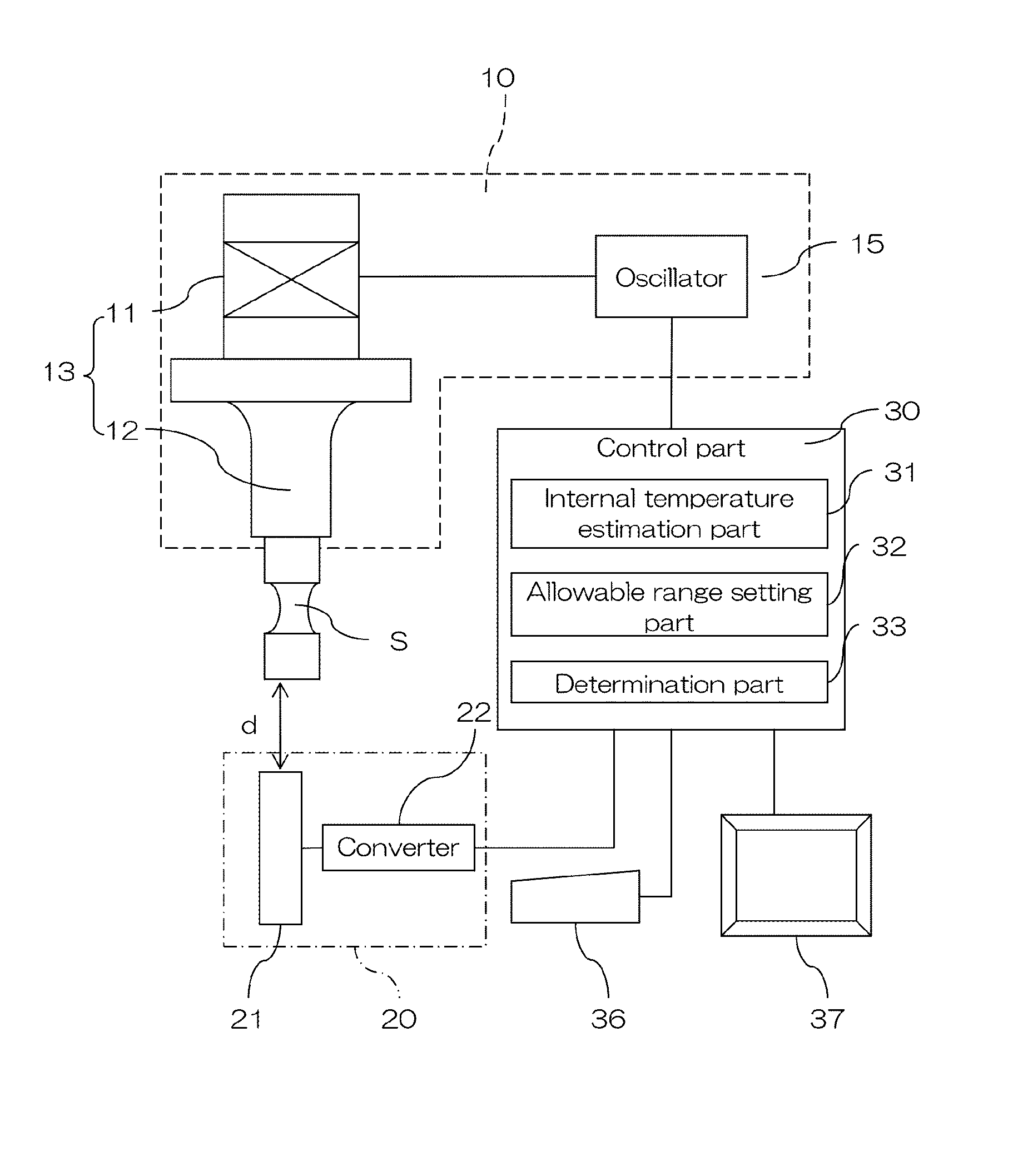
[0023]An embodiment of the present invention is described below on the basis of the drawings. FIG. 1 is a schematic diagram illustrating a main configuration of an ultrasonic fatigue testing machine of this invention.

[0024]The ultrasonic fatigue testing machine is one that resonates a test piece S by an ultrasonic wave to perform a fatigue test, and configured to include an ultrasonic wave generation part 10, a displacement measurement part 20, and a control part 30 that controls the overall operation of the ultrasonic fatigue testing machine.

[0025]The ultrasonic wave generation part 10 has: an oscillation part 13 that includes an ultrasonic transducer 11 and a horn 12; and an oscillator 15 that prepares a signal for oscillating the ultrasonic transducer 11. The oscillator 15 prepares the electrical signal on the basis of a test frequency set in the control part 30. The ultrasonic transducer 11 is driven by the electrical signal outputted from the oscillator 15, and generates ultras...


PUM


Abstract

This ultrasonic fatigue testing machine is one that resonates a test piece by an ultrasonic wave to perform a fatigue test, and configured to include an ultrasonic wave generation part 10, a displacement measurement part 20, and a control part 30 that controls the overall operation of the ultrasonic fatigue testing machine. The control part 30 is configured to have a computer that includes storage devices capable of store programs and various types of data, such as an RAM and an ROM, and an arithmetic unit such as a CPU, and includes an internal temperature estimation part 31, an allowable range setting part 32, and a determination part 33 as a main functional configuration.

Description

TECHNICAL FIELD[0001]The present invention relates to an ultrasonic fatigue testing machine and ultrasonic fatigue testing method that resonate a test piece by an ultrasonic wave to perform a fatigue test.BACKGROUND ART[0002]There has been conventionally known an ultrasonic fatigue test that evaluates a fatigue life of a metallic material or the like by using an ultrasonic wave to oscillate a test piece. In such an ultrasonic fatigue test, stress is repetitively loaded on a test piece by resonating the test piece with, for example, sine wave oscillation at 20 kHz.[0003]On the other hand, in the ultrasonic fatigue test, the high-frequency repetitive load is applied to the test piece, and therefore a rise in temperature of the test piece caused by the internal heat generation of a material becomes problematic. For this reason, there has been proposed an ultrasonic fatigue testing machine that measures temperature near a test piece during a test, and when the temperature reaches a pred...

Claims


Application Information

Patent Timeline
IPC IPC(8): G01M7/02G01N29/04
CPCG01M7/022G01N29/04G01N2291/02827G01N2291/0289G01N2291/0234G01N2203/0008G01N2291/0258
Inventor MATSUURA, TOHRU
Owner SHIMADZU CORP
Why Eureka
Try Eureka