Ring binder mechanism

a ring binder and mechanism technology, applied in the field of ring binder mechanism, can solve the problems of inconvenient opening or closing the ring binder by both hands, increase in cost, etc., and achieve the effects of convenient operation, simple structure, and convenient operation

Active Publication Date: 2015-08-20
CHUNG TIN INT
View PDF5 Cites 1 Cited by
  • Summary
  • Abstract
  • Description
  • Claims
  • Application Information

AI Technical Summary

Benefits of technology

[0012]The first embodiment described herein is intended to effectively overcome the shortcomings in technology stated above, and provide an automatic cyclic ring binder mechanism that has a simple structure, can accomplish the open-closing cycle when being pushed by one hand cyclically, and be operated comfortably, easily, simply and conveniently, thus reducing the cost of use.
[0023]The benefits of first embodiment disclosed herein are as follows: the automatic cyclic ring binder mechanism has a simple structure, can accomplish the open-closing cycle when being pushed by one hand cyclically through the actions of positioning and locking by automatically revolving push rod positioning bush arranged in the push rod, recoil spring and push members, and be operated comfortably, easily, simply and conveniently, thus reducing the cost of use and meeting the market demand.
[0024]The second embodiment described herein is intended to effectively overcome the shortcomings in technology stated above, and provide a single hand-operated binder mechanism that has a simple structure, can be opened or closed with one hand, and be operated comfortably, easily, simply and conveniently, thus reducing the cost of use.
[0031]The single hand-operated ring binder mechanism disclosed in this embodiment brings about the following beneficial results: to open the ring binder mechanism, use one hand to press the button on the push member, which will result in that the button is separated from the ledge and released; the draw spring returns to the original position; the drawbar is pulled by the draw spring and moves; the horizontal parts of the top bars are separated from the clamping slot; the inclined parts of the top bars prop up the hinge boards; each pair of semi-rings is separated from each other, thus the ring binder mechanism is opened; to close the ring binder mechanism, use one hand to press the button on the push member and push the drawbar to move toward the housing longitudinally; when the push member is at the opening, the button is released, the button makes contact with the ledge, the draw spring is pulled, the top bars are clamped in the clamping slot, the hinge boards return to their original positions, and each pair of semi-rings is engaged, thus the ring binder mechanism is closed. It has a simple structure, can be opened or closed with one hand without requiring high physical strength of the hand, has nice hand feel, and can be operated comfortably, easily, simply and conveniently; particularly, when the ring binder mechanism contains a large number of leaflets. It can be conveniently opened or closed with one hand, thus saving both time and labor, reducing the cost of use and meeting the market demand.
[0032]The objective of this invention is to overcome the defects of the technique above and provide a push-tab single-hand binder. Only one hand is required to open or close the binder. It's very pleasant, easy and convenient to handle the binder. It can save a lot of manpower and reduce costs.
[0038]This practical invention has the advantages that: the invention relates to a push-tab single-hand binder, wherein when the binder needs to be opened, use one hand to press the push button; the spring is compressed, the connecting rod and the fixed block move downward along with the pressing of the push button; the moving of the fixed block drives the movement of the right end of the movable connecting rod downward, causing the sloping block's detachment from the right side surface of the base plate; when the right end of the sloping block is located at the recess on the right surface of the base plate, the tension spring returns, driving the movement of the tension rod toward the right; the horizontal part of the top bar detaches from the slot; the inclined part of the top bar jacks up the hinge plate; every pair of the half-ring elements are separated, and the binder is open. When the binder needs to be closed, use one hand to push the push member toward the left; the tension rod moves toward the left; the spring is extended gradually; the sloping block is pressed by the recess while it's going through the recess that is on the right end surface of the base plate, causing the right end of the movable connecting rod to move downward gradually; this also drives the fixed block, the connecting rod and the push button to move downward gradually; the spring is compressed gradually; the spring returns when the sloping block goes through the breach, driving the push button, the connecting rod and the fixed block to move upward; the movement of the fixed block drives the right end of the movable connecting rod to move upward; the right end of the sloping block leans against the right end inner surface of the base plate; the spring is extended fully; the horizontal part of the top bar snaps into the slot; the inclined part of the top bar has no force with the hinge plate; the hinge plate returns; every pair of the half-ring elements are closed, and the binder is closed. This practical invention has a simple structure. One hand is required to open or close it. Manpower is not required. It can be opened easily with little strength. It is easy on the hands. It's very comfortable, easy and convenient to handle the binder. Using one hand to open or close the binder is very convenient, especially when excessive amounts of papers are added. It's time and effort saving. It has long service duration and reduces cost. It meets consumers' demand greatly. It will be appreciated that although the embodiments discussed herein can be opened with one hand, this is not a limitation on the present invention and two hands can be used.

Problems solved by technology

In addition, the operation by both hands will cause an uncomfortable feel and have the problem of uneven strength between the hands, which is likely to damage the ring binder, resulting in increase in cost.
When there are a large number of leaflets within the semi-rings, it will be very inconvenient to open or close the ring binder by both hands.

Method used


Image

  • Ring binder mechanism
  • Ring binder mechanism
  • Ring binder mechanism

Examples


first embodiment

[0012]The first embodiment described herein is intended to effectively overcome the shortcomings in technology stated above, and provide an automatic cyclic ring binder mechanism that has a simple structure, can accomplish the open-closing cycle when being pushed by one hand cyclically, and be operated comfortably, easily, simply and conveniently, thus reducing the cost of use.

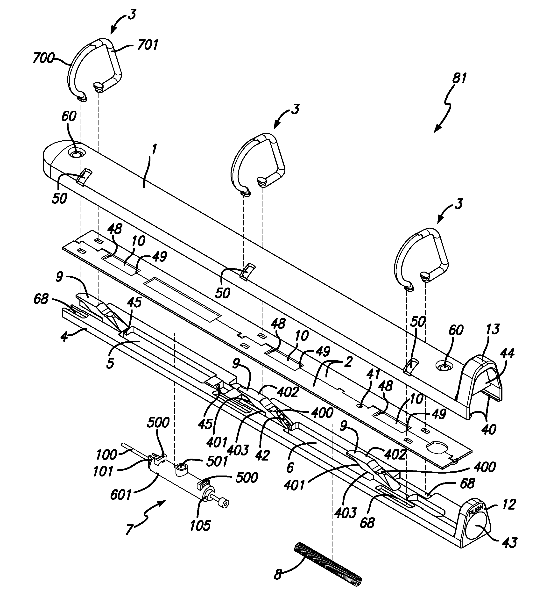
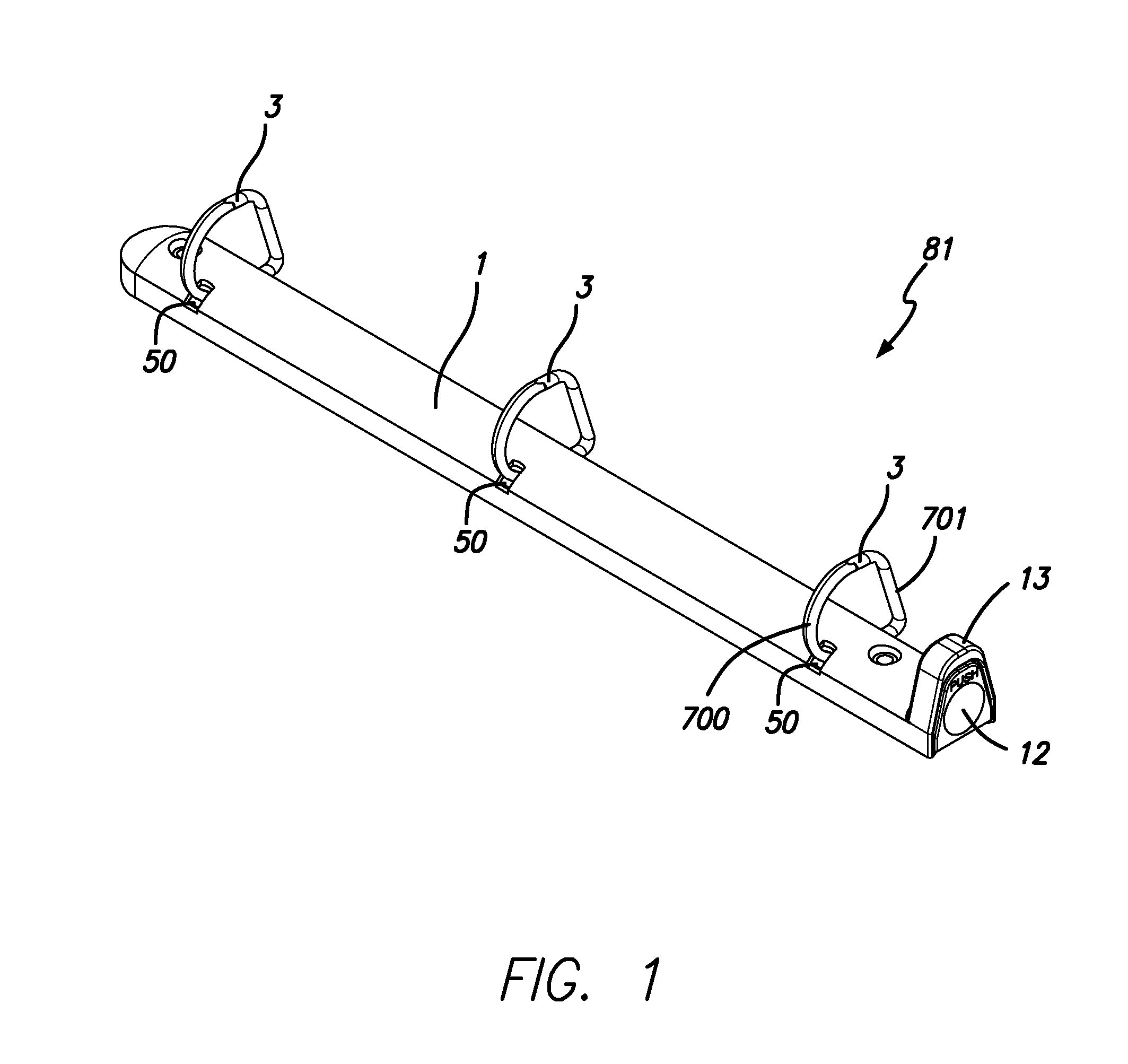
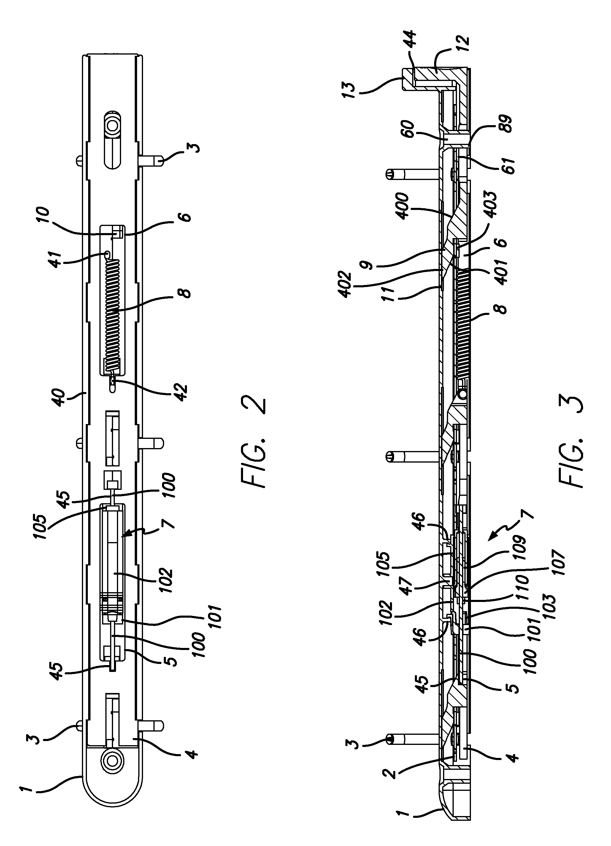
[0013]The technical solution of the first embodiment disclosed herein is as follows: it comprises a housing, a pair of pivotable hinge boards inside the housing and clamped tightly by the housing, and a plurality of pairs of semi-rings secured on the hinge boards respectively; the semi-rings protrude from the upper surface of the housing. The automatic cyclic ring binder mechanism is characterized by the fact that it further comprises a push rod inside the housing that can move along the axis of the housing; the push rod is located beneath the hinge boards; a first straight slot and a second straight slot are ...

second embodiment

[0024]The second embodiment described herein is intended to effectively overcome the shortcomings in technology stated above, and provide a single hand-operated binder mechanism that has a simple structure, can be opened or closed with one hand, and be operated comfortably, easily, simply and conveniently, thus reducing the cost of use.

[0025]The technical solution of the second embodiment disclosed herein is as follows: it comprises a housing, a pair of pivotable hinge boards inside the housing and clamped tightly by the housing, and a plurality of pairs of semi-rings secured on the pair of hinge boards respectively. The improvement made in it is that it further comprises a drawbar installed inside the housing that can move along the housing longitudinally; the drawbar is located beneath the hinge boards; a draw spring and a plurality of top bars are arranged on the drawbar; the top bars are used for propping up the hinge boards; a push member is arranged at one end of the drawbar; ...

third embodiment

[0033]In order to achieve this objective, a proposal for this practical invention is shown here: The third embodiment binder comprises a base plate with an opening at the end, a pair of pivoting hinge plates, and several pairs of half-ring elements, wherein a tension rod is installed inside the base plate and movable along the axis direction of the base plate; this tension rod is located below the hinge plates; along the axis direction of the tension rod, there is a tension spring and several top bars for jacking up the hinge plates; the tension spring is connected to the hinge plates; the top bars mentioned above extend from the hinge plates, and the upper end of the top bars snaps into a slot which is located on the top of the base plate's inner surface; a push member is attached to the right side of the tension rod, they are integrated into a whole; this push member is located at the opening of the right side of the base plate; a through chamber is located on the push member; the...


PUM


Abstract

A ring binder mechanism that includes a housing, first and second hinge boards positioned in the housing that cooperate to define a slot having a closing edge and an opening edge. The hinge boards are pivotable between open and closed positions. A plurality of pairs of semi-rings include first and second ring members mounted on the first and second hinge boards, respectively. A travel bar is positioned below the hinge boards and moveable with respect to the housing and the hinge boards between an open position and a closed position. The travel bar includes at least one top bar extending from a top surface thereof that includes inclined opening and closing surfaces. The top bar extends through the slot in the hinge boards and is biased toward the open position. The inclined opening surface of the top bar contacts the opening edge of the slot to pivot the first and second hinge boards to the open position.

Description

FIELD OF THE INVENTION[0001]The present invention relates to a ring binder mechanism for holding loose leaf paper.BACKGROUND OF THE INVENTION[0002]A ring binder is a stationary accessory, generally called loose-leaf binder in the art. It can protect documents securely and safely, ensure smooth flipping of documents and will not scratch documents. The hook-rings can be tightly engaged. It features an elegant appearance and a stable structure and is unlikely to be scratched or sink in. The whole binder has a high strength and is unlikely to become deformed. A binder generally comprises a long bar-shaped housing, a pair of pivotable hinge boards inside the housing and clamped tightly by the housing, and semi-rings secured on the hinge boards. The semi-rings can be opened or closed by the pivoting of the hinge boards. When they are closed, the ends of the two corresponding semi-rings on the two hinge boards are pressed together, so that the two semi-rings form a complete hook-ring, to f...

Claims


Application Information

Patent Timeline
Patent Type & Authority Applications(United States)
IPC IPC(8): B42F13/22
CPCB42F13/26B42F13/36B42F13/22B42F13/20B42F13/16
Inventor ZHONG, JIAGUI
Owner CHUNG TIN INT
Why Eureka
Try Eureka