Electronic simulation candle
a simulation candle and electronic technology, applied in the field of decorative illumination, can solve the problems of limited simulation degree, visual aesthetics will be destroyed by the support rod, visual aesthetics will be destroyed by the wire, etc., and achieve the effect of low simulation degree, not so realistic, and realistic flame flickering
- Summary
- Abstract
- Description
- Claims
- Application Information
AI Technical Summary
Benefits of technology
Problems solved by technology
Method used
Image

Examples
first embodiment
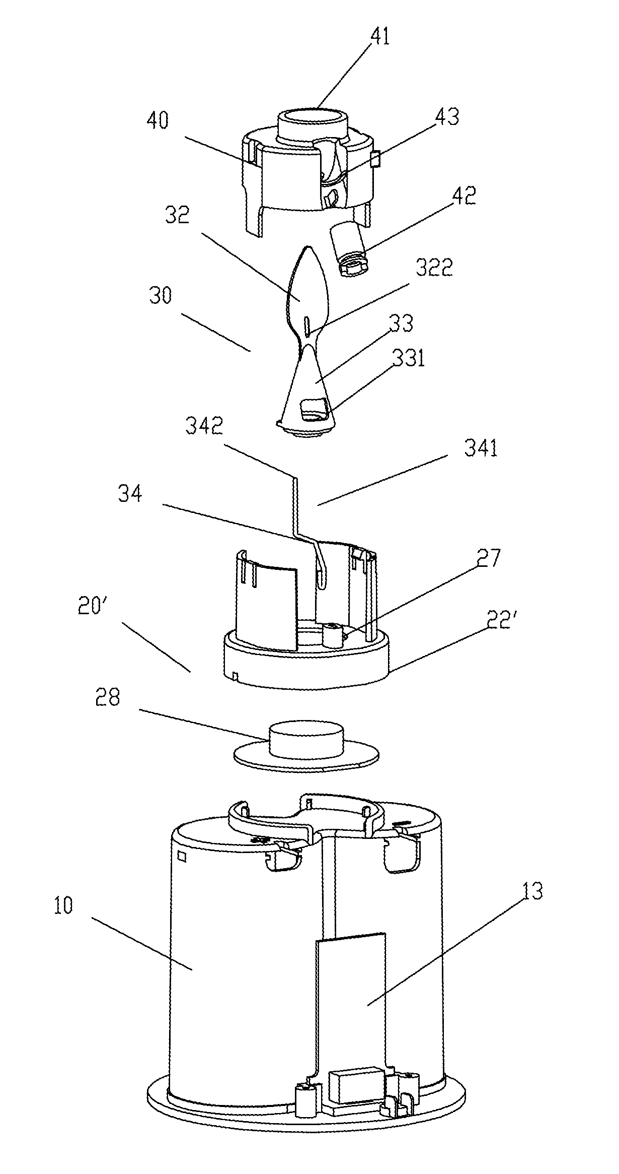
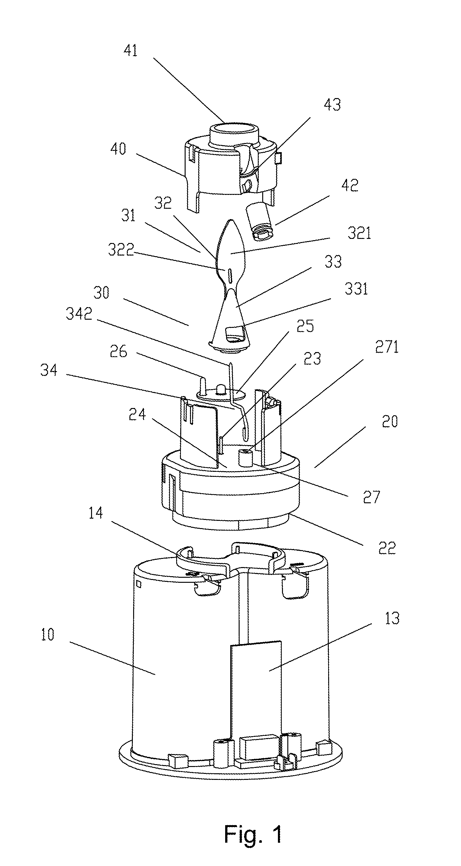
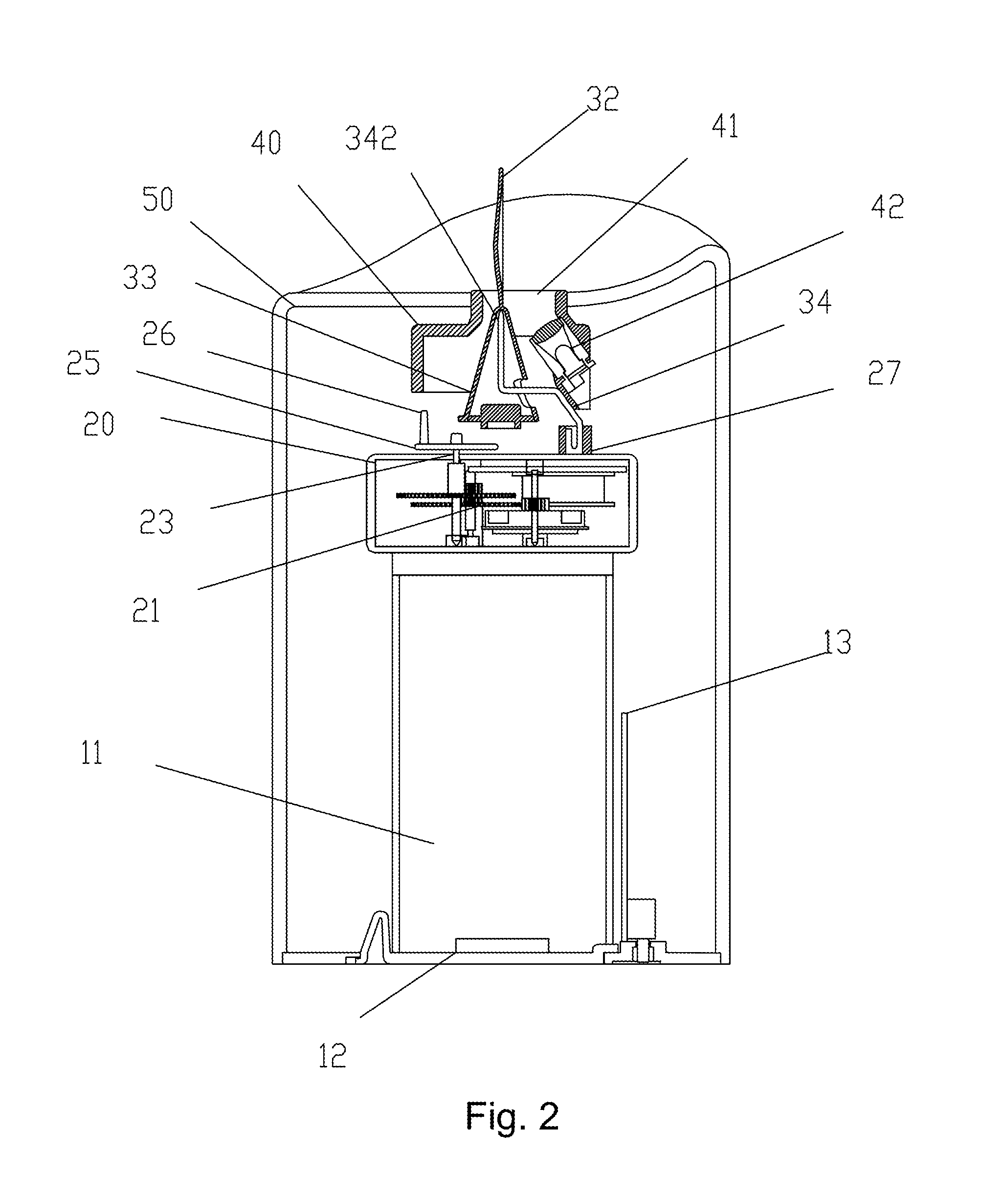
[0045]FIG. 1 to FIG. 3 show the present invention. The disclosed electronic simulation candle mainly comprises a power supply base 10, a power driven device 20, a flame piece swinger 30 and a light source fixation base 40. The power driven device 20 is electrically connected to the power supply base 10 and disposed above the power supply base 10. The light source fixation base 40 is disposed above the power driven device 20. The flame piece swinger 30 is disposed between the power driven device 20 and the light source fixation base 40. The power supply base 10 is an upright base having an accommodation space 11 therein, which accommodation space 11 can be used for accommodating batteries (not shown) and then closed via a cover plate 12 on the bottom thereof. A circuit board 13 electrically connected to the power supply base 10 is provided outside the power supply base 10. A fixed base 14 is disposed in the top center of the power supply 10.
[0046]The power driven device 20 consists o...
third embodiment
[0054]In addition, FIG. 6 shows the present invention. A modification is that the fixed column 27′ for inserting the support rod 34 is provided on the outer side of the upper surface of the turntable 25′. In addition, left and right limiting stand columns 29 and 29′ are provided on the chassis 22′ outside the turntable 25′. A positioning driving lever 251′ (as shown in FIG. 7) extending outward and rightly positioned between the left and right limiting stand columns 29 and 29′ is provided on the outer edge of the turntable 25′. The gear set 21 is enabled by the control of the circuit board 13 to drive the positioning driving lever 251′ to rotate forwardly to push the right limiting stand column 29′ and to rotate backwardly to push the left limiting stand column 29. In such an order, the turntable 25′ continuously rotates forwardly and backwardly, so that the flame piece swinger 30 may swing back and forth around the top 342 of the support rod 34, and the flame piece body 32 generate...
fourth embodiment
[0056]FIG. 9 is the present invention. The electronic simulation candle 60 as disclosed comprises a simulation candle shell 62 having a spiral fixed conductive plug 61 at its bottom end, a power driven device 20, a flame piece swinger 30 and a light source fixation base 40; the spiral fixed conductive plug 61 is electrically connected to a circuit board 63 provided within the simulation candle shell 62; the power driven device 20 is electrically connected to the circuit board 63 and also disposed above the circuit board 63; the light source fixation base 40 is disposed on an inner side wall of the top end of the simulation candle shell 62; the flame piece swinger 30 is disposed at the top end of the simulation candle shell 62, and the upper half of the flame piece swinger 30 is a flame piece body 32 which extends upward out from the top end of the simulation candle shell 62 and has a concave surface 321; a hollow tapered swinger 33 expanding gradually from up to down is integrally d...
PUM
 Abstract
Description
Claims
Application Information
 - R&D
- Intellectual Property
- Life Sciences
- Materials
- Tech Scout
- Unparalleled Data Quality
- Higher Quality Content
- 60% Fewer Hallucinations
Browse by: Latest US Patents, China's latest patents, Technical Efficacy Thesaurus, Application Domain, Technology Topic, Popular Technical Reports.
© 2025 PatSnap. All rights reserved.Legal|Privacy policy|Modern Slavery Act Transparency Statement|Sitemap|About US| Contact US: help@patsnap.com