System and method for improving the accuracy of a rate of decay measurement for real time correction in a mass flow controller or mass flow meter by using a thermal model to minimize thermally induced error in the rod measurement

a technology of mass flow controller and thermal model, which is applied in the direction of water supply installation, process and machine control, instruments, etc., can solve the problems of thermally induced errors in current rate of decay measurement, and achieve the effect of minimizing thermally induced errors in improving the accuracy of the rate of decay measuremen

Active Publication Date: 2015-08-20
ILLINOIS TOOL WORKS INC
View PDF7 Cites 8 Cited by
  • Summary
  • Abstract
  • Description
  • Claims
  • Application Information

AI Technical Summary

Benefits of technology

[0007]The disclosed embodiments include a method, apparatus, and computer program product for improving the accuracy of a rate of decay measurement for real time correction in a mass flow controller (MFC) and / or a mass flow meter (MFM) by using a thermal model to minimize thermally induced error in the rate of decay measurement.
[0008]For example, in one embodiment, a mass flow controller is disclosed that includes an inlet for receiving the fluid and a flow path in which the fluid passes through the mass flow controller. The mass flow controller also includes a mass flow sensor for providing a signal corresponding to mass flow of the fluid through the flow path; an adjustable valve for regulating a flow of the fluid out of an outlet of the mass flow controller; and a controller configured to apply a valve control signal to adjust the adjustable valve to a desired valve position to control the flow of the fluid out of an outlet of the mass flow controller. Further, in accordance with the disclosed embodiments, the mass flow controller includes at least one processing component configured to execute instructions to improve the accuracy of a rate of decay measurement by using a thermal model to minimize thermally induced error in the rate of decay measurement.

Problems solved by technology

However, current rate of decay measurements may include a thermally induced error.

Method used


Image

  • System and method for improving the accuracy of a rate of decay measurement for real time correction in a mass flow controller or mass flow meter by using a thermal model to minimize thermally induced error in the rod measurement
  • System and method for improving the accuracy of a rate of decay measurement for real time correction in a mass flow controller or mass flow meter by using a thermal model to minimize thermally induced error in the rod measurement
  • System and method for improving the accuracy of a rate of decay measurement for real time correction in a mass flow controller or mass flow meter by using a thermal model to minimize thermally induced error in the rod measurement

Examples


Embodiment Construction

[0022]The disclosed embodiments include a system and method for improving the accuracy of a rate of decay measurement for real time correction in a mass flow controller or mass flow meter by using a thermal model to minimize thermally induced error in the rate of decay measurement.

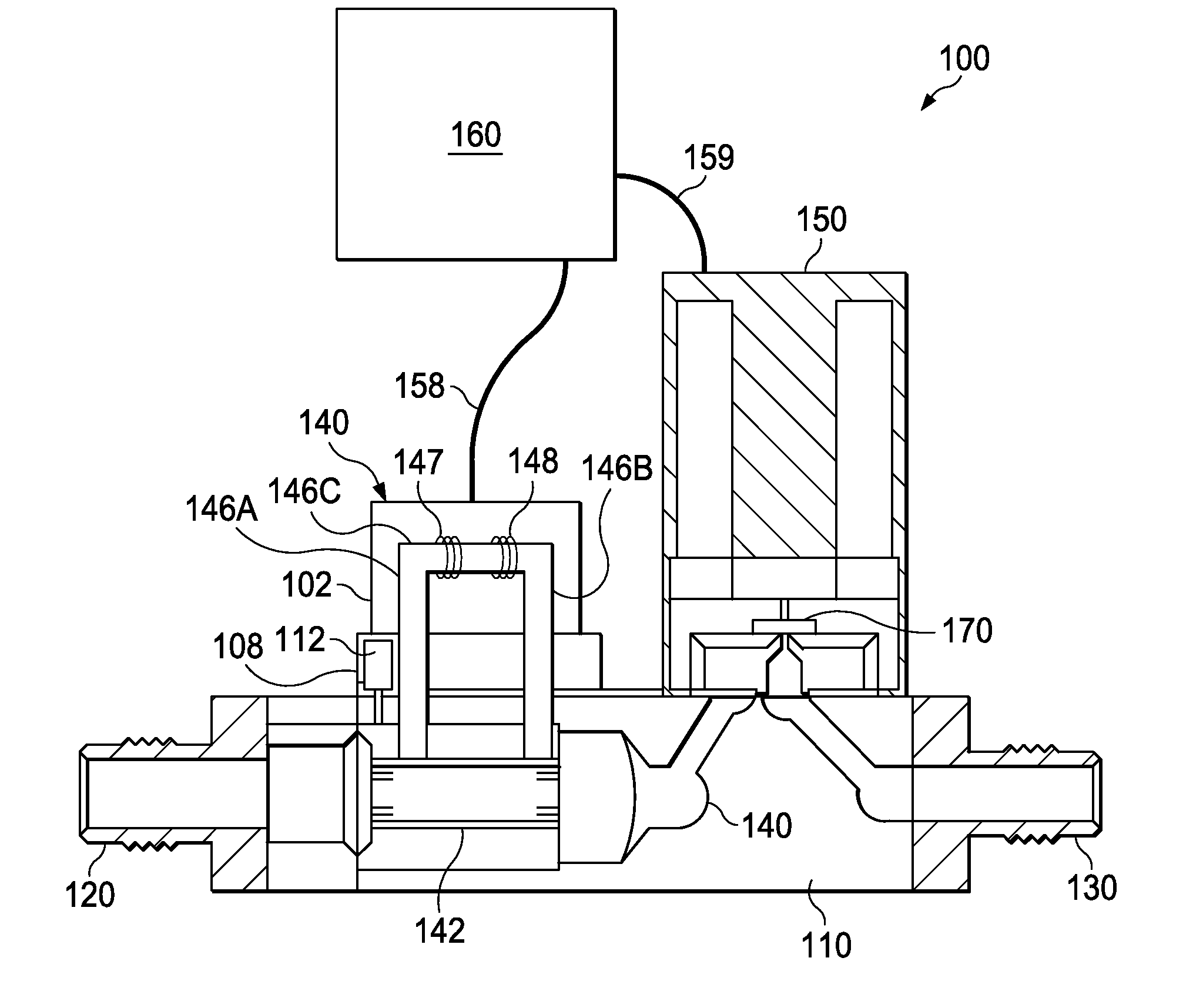
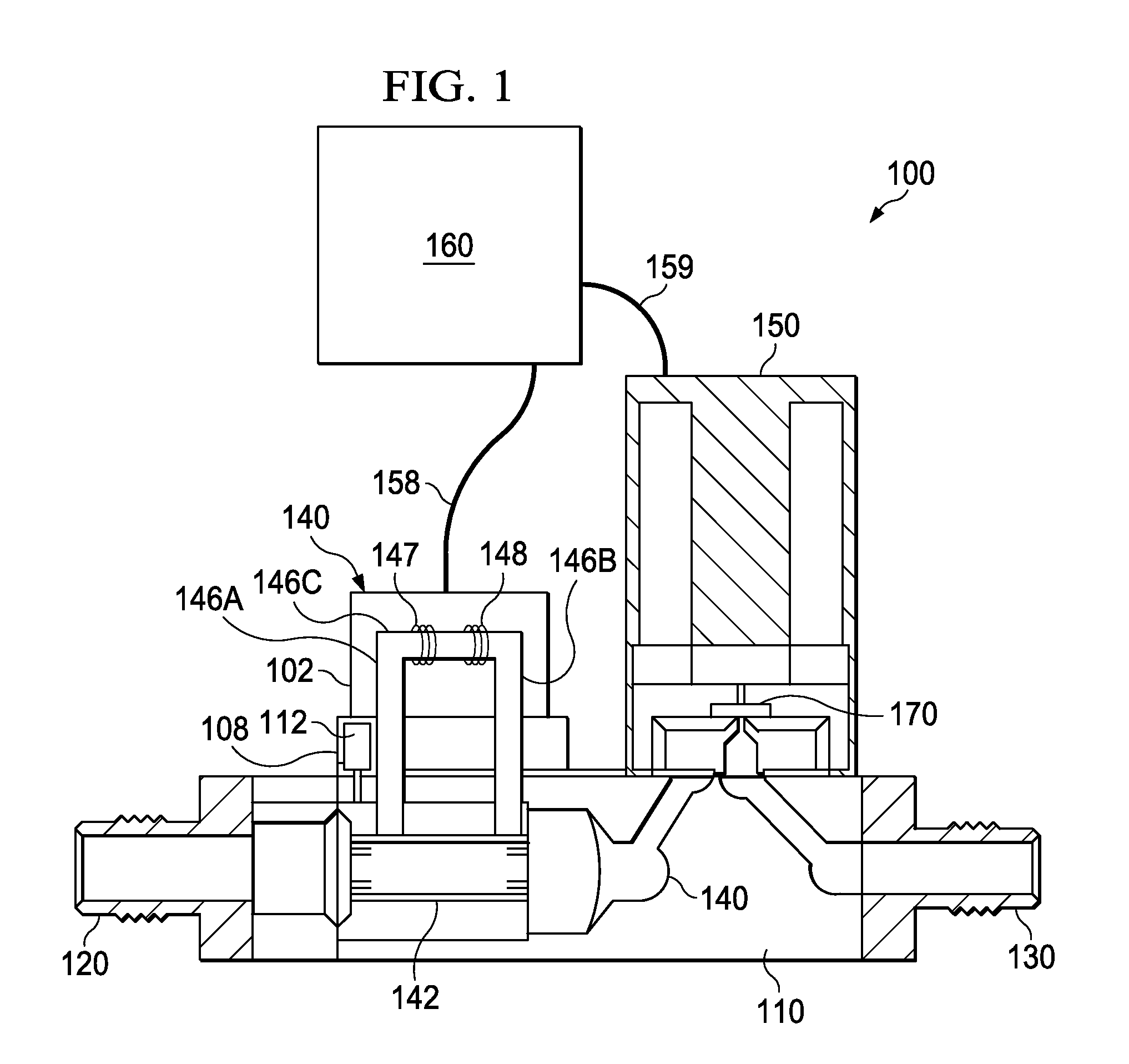
[0023]The disclosed embodiments and advantages thereof are best understood by referring to FIGS. 1-10 of the drawings, like numerals being used for like and corresponding parts of the various drawings. Other features and advantages of the disclosed embodiments will be or will become apparent to one of ordinary skill in the art upon examination of the following figures and detailed description. It is intended that all such additional features and advantages be included within the scope of the disclosed embodiments. Further, the illustrated figures are only exemplary and are not intended to assert or imply any limitation with regard to the environment, architecture, design, or process in which different embo...


PUM


Abstract

The disclosed embodiments include a method, apparatus, and computer program product for improving the accuracy of a rate of decay measurement for real time correction in a mass flow controller or mass flow meter by using a thermal model to minimize thermally induced error in the rate of decay measurement.

Description

BACKGROUND OF THE INVENTION[0001]1. Field of the Invention[0002]The present invention relates generally to methods and systems for determining the mass flow rate of a fluid, and more particularly to the operation of mass flow controllers.[0003]2. Discussion of the Related Art[0004]Many industrial processes require precise control of various process fluids. For example, in the semiconductor industries, mass flow meters (MFMs) are used to precisely measure the amount of a process fluid that is introduced to a process chamber. In addition to measuring the mass flow, mass flow controllers (MFCs) are used to precisely measure and control the amount of a process fluid that is introduced to a process chamber. It is to be understood that the term fluid as used herein applies to any type of gas or vapor to which controlled flow may be of interest.[0005]Rate of decay (ROD) measurements can be used to calibrate a variety of flow measurement devices including mass flow controllers and mass flow...

Claims


Application Information

Patent Timeline
Patent Type & Authority Applications(United States)
IPC IPC(8): G05D7/06G01F25/00
CPCG01F25/00G05D7/06G01F1/6847G01F1/86G01F15/005G05D7/0635Y10T137/0324Y10T137/7722G01F25/15G01F25/10
Inventor KEHOE, ANTHONYBANARES, BERWINELLEC, CHRISLULL, JOHNVALENTINE, WILLIAM
Owner ILLINOIS TOOL WORKS INC
Why Eureka
Try Eureka