Operation system
a technology of operation system and operation system, applied in the field of operation system, can solve the problem of low operability of the operation system, and achieve the effect of improving operability
- Summary
- Abstract
- Description
- Claims
- Application Information
AI Technical Summary
Benefits of technology
Problems solved by technology
Method used
Image
Examples
first embodiment
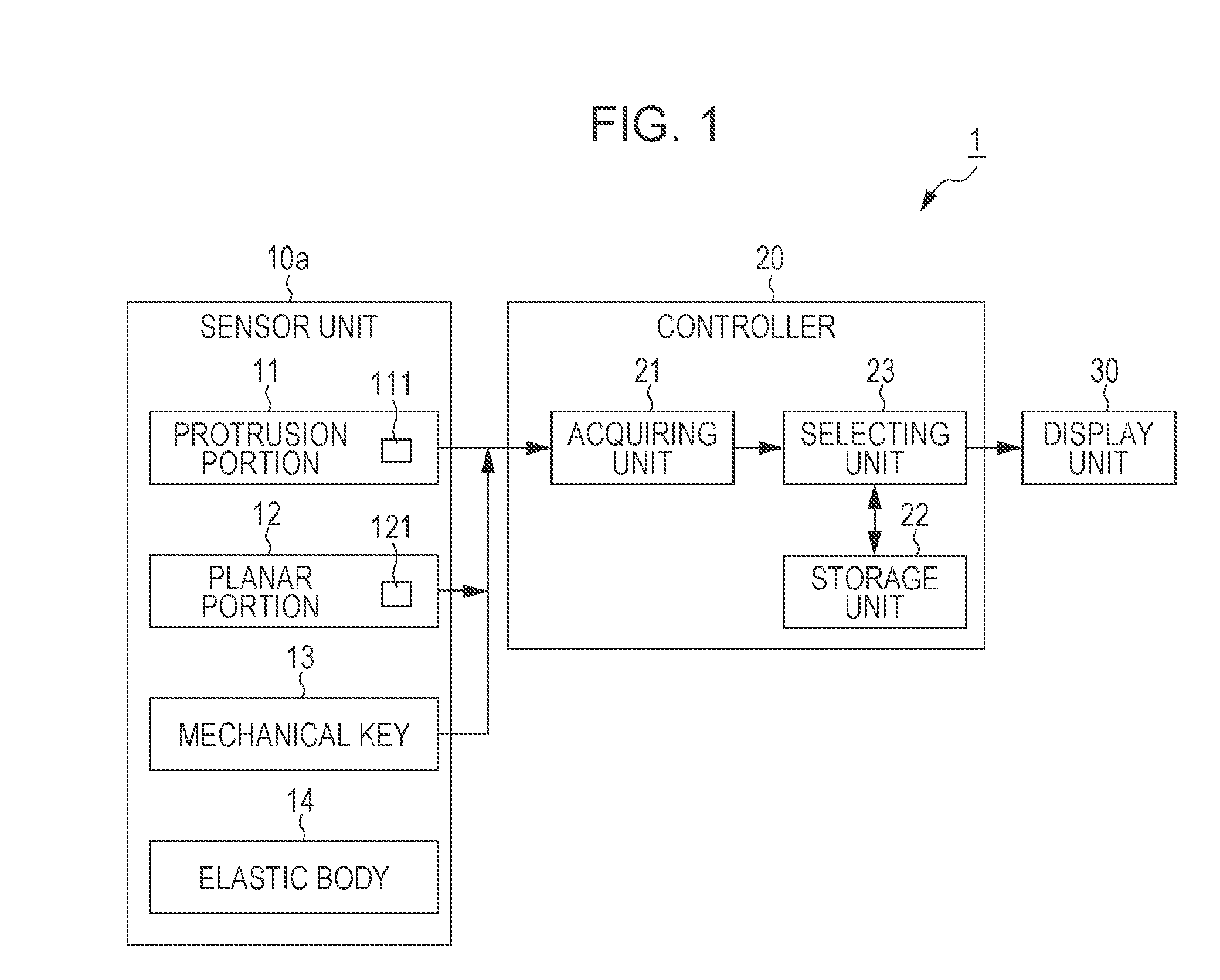
[0035]FIG. 1 is a diagram illustrating an exemplary configuration of an operation system 1 according to a first embodiment. The operation system 1 controls electronic equipment such as equipment installed in an automobile in accordance with a signal according to an operation performed by an operator. The operation system 1 is mounted, for example, on a vehicle. The operation system 1 includes a sensor unit 10a, a controller 20, and a display unit 30.
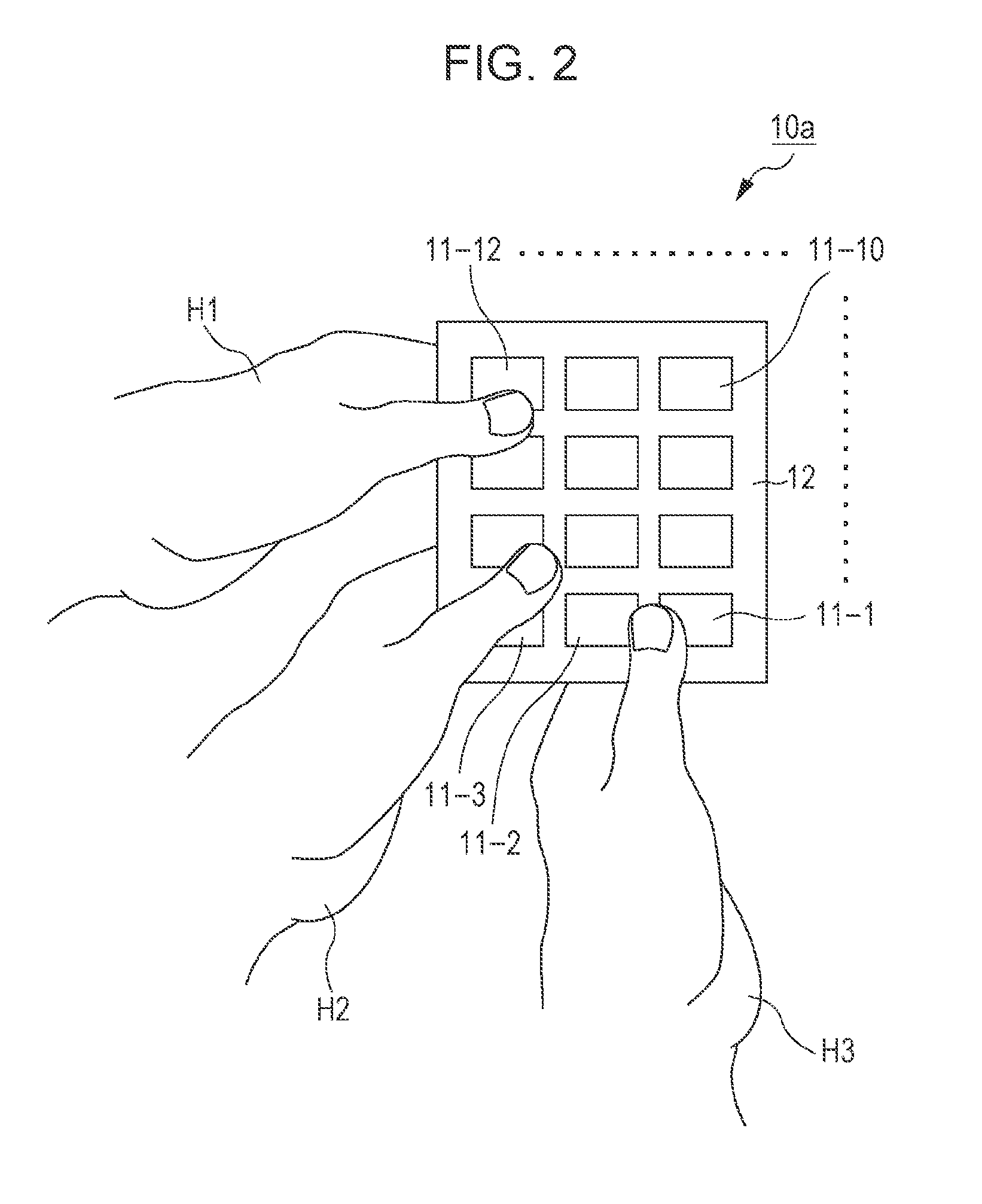
[0036]The sensor unit 10a has multiple protrusion portions 11 arranged in a matrix and a planar portion 12, on the surface thereof as a structure with unevenness such as protrusions and depressions. The protrusion portions 11 may be depression portions. That is, on the surface of the sensor unit 10a, there are positions within the protrusion portions 11 and positions outside of the protrusion portions 11. Each of the protrusion portions 11 includes a touch sensor 111. The protrusion portion 11 is capable of detecting a position which is ...
second embodiment
[0099]A second embodiment is different from the first embodiment in that the number of protrusion portions 11 is more than that of operation key images 210. In the second embodiment, only differences between the first and second embodiments will be described.
[0100]FIG. 14 is a front view of an exemplary configuration of a sensor unit 10b according to the second embodiment. The sensor unit 10b includes the protrusion portions 11-20 to 11-43 arranged in a matrix and the planar portion 12, as a structure with protrusions and depressions, on the surface thereof. In FIG. 14, the protrusion portions 11 are, for example, arranged in a 4×6 matrix. The protrusion portions 11 may be depression portions.
[0101]In FIG. 14, the number of protrusion portions 11 is more than that of operation key images 210. Therefore, the position signal may be represented by using relative coordinates on the surface of the sensor unit 10b. An operator performs a slide operation on the surface of the sensor unit 1...
third embodiment
[0106]A third embodiment is different from the first and second embodiments in that an optical sensor detects the position of a contact body. In the third embodiment, differences between the first or second embodiment and the third embodiment will be described.
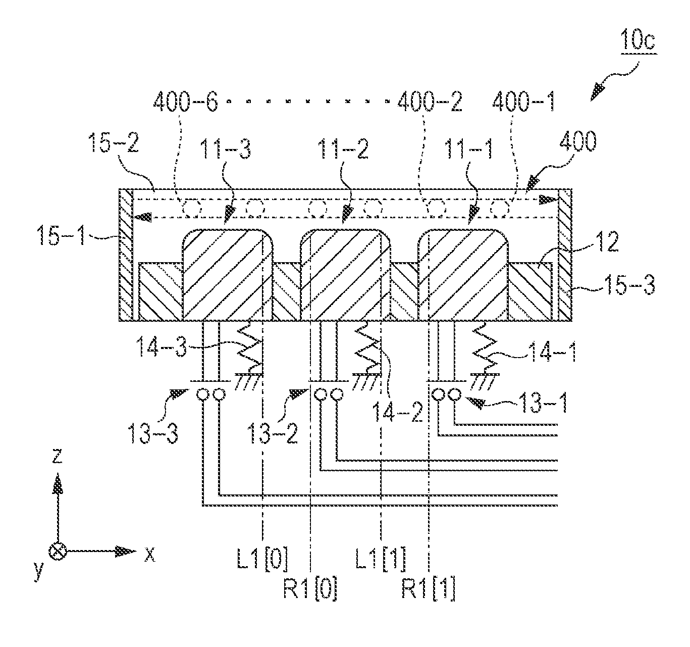
[0107]FIG. 16 is a diagram illustrating an exemplary configuration of the operation system 1 according to the third embodiment. The operation system 1 includes a sensor unit 10c, the controller 20, and the display unit 30. Compared with the sensor unit 10a according to the first embodiment, the sensor unit 10c further includes optical sensors 15. The optical sensors 15 emit light beams such as infrared rays in predetermined directions, and detect the position of a contact body such as an operator's finger on the basis of the position at which light beams are cut off.
[0108]FIG. 17 is a front view of an exemplary configuration of the sensor unit 10c according to the third embodiment. The optical sensors 15 are disposed in such a...
PUM
 Abstract
Description
Claims
Application Information
 - R&D
- Intellectual Property
- Life Sciences
- Materials
- Tech Scout
- Unparalleled Data Quality
- Higher Quality Content
- 60% Fewer Hallucinations
Browse by: Latest US Patents, China's latest patents, Technical Efficacy Thesaurus, Application Domain, Technology Topic, Popular Technical Reports.
© 2025 PatSnap. All rights reserved.Legal|Privacy policy|Modern Slavery Act Transparency Statement|Sitemap|About US| Contact US: help@patsnap.com


