Unitized energy storage system enclosure

Active Publication Date: 2015-08-20
UNIQUE ELECTRIC SOLUTIONS INC
View PDF2 Cites 4 Cited by
  • Summary
  • Abstract
  • Description
  • Claims
  • Application Information

AI Technical Summary

Benefits of technology

[0039]An advantage of an apparatus and method according to aspects of the invention is that the enclosure facilitates the elimination of the typical isolative wrapping on the electrical energy storage device to enhance thermal conductivity and maintain electrical isolation.
[0040]Another advantage of an apparatus and method according to aspects of the invention is that is that the enclosure exerts a uniform rad

Problems solved by technology

Although many of these electrical energy storage devices offer improved performance (resulting in longer life and vehicle range), they still suffer from thermal management challenges.
Heating causes a number of problems for any electrical energy storage device.
(1) thermal cycling which causes dimensional instability (swelling) and results in degradation of the electrical energy storage device enclosure and an increase of the internal electrical conductive paths of the electrical energy storage device, which further increases the internal resistance (and heating) and results in a lower operating voltage;
(2) chemical breakdown of the internal electrical energy storage device structure from elevated temperatures; and
(3) thermal runaway (uncontrolled heating).
Electrical energy storage device usage patterns, especially for large demand applicatio

Method used


Image

  • Unitized energy storage system enclosure
  • Unitized energy storage system enclosure
  • Unitized energy storage system enclosure

Examples


Example

DETAILED DESCRIPTION OF THE DRAWINGS

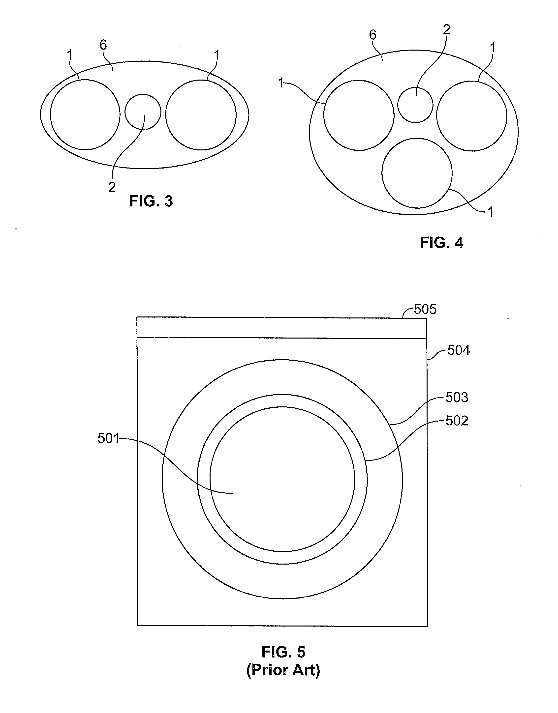
[0051]To better appreciate the present invention, some deficiencies with respect to the prior art are illustrated in FIG. 5. In particular, prior art battery enclosure designs include a number of physical interfaces associated with their construction. As shown in FIG. 5, the electrical energy storage device (e.g. cell) itself 501 is surrounded by an isolation wrapping 502, a conductive bridge 503, an enclosure body 504, and then a heat sink 505 is attached. Each interface boundary localizes a buildup of stored heat which has disadvantageous reliability and performance issues.

[0052]The elimination of the isolation wrapping 502 and the conductive bridge 503 would eliminate four thermal interfaces in the construction of the enclosure module.

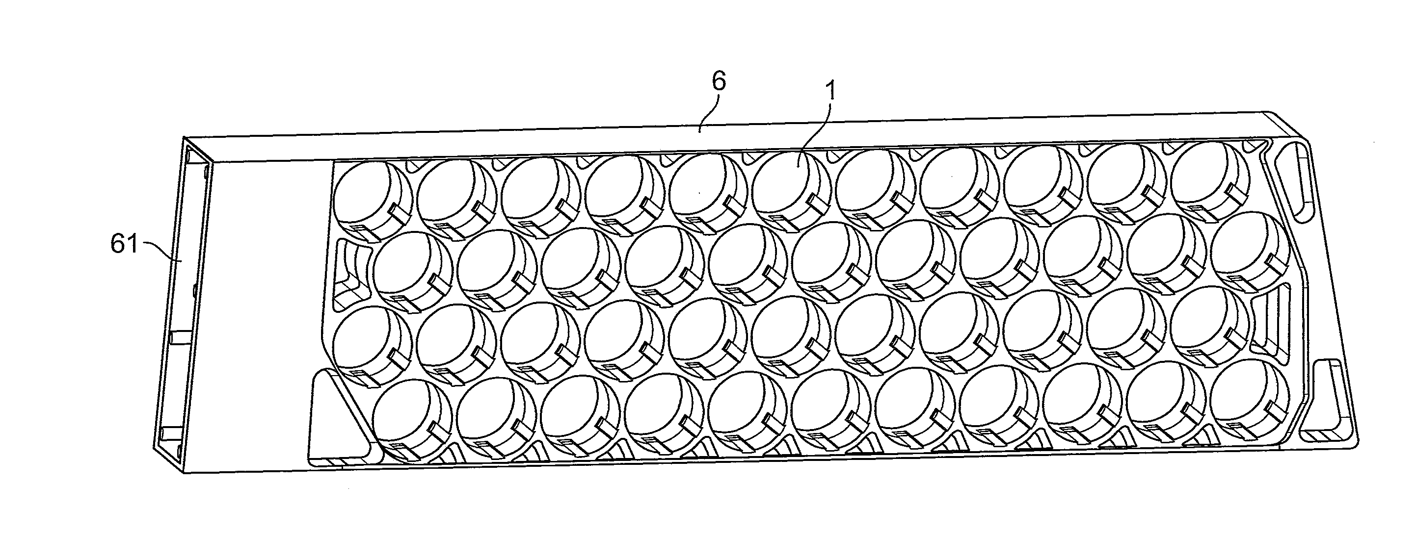
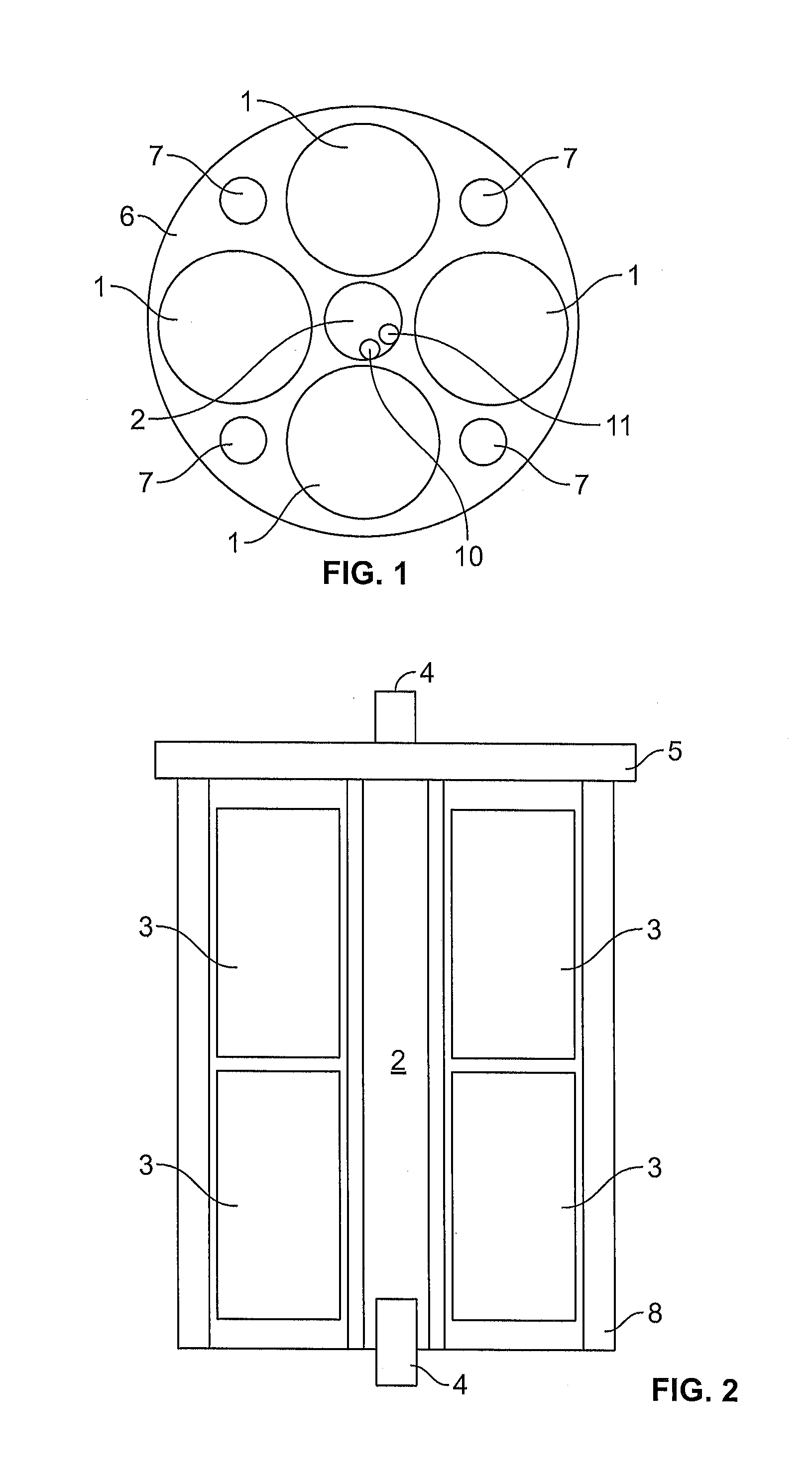
[0053]FIG. 1 shows a top view of thermally managed electrical energy storage device enclosure according to an embodiment of the invention. The enclosure includes a monocoque body 6 formed from a plastic material u...


PUM

PropertyMeasurementUnit
Temperatureaaaaaaaaaa
Forceaaaaaaaaaa
Shapeaaaaaaaaaa

Abstract

A thermally managed electrical energy storage device enclosure includes a monocoque body formed from a plastic material using a single batch process and at least one void defined by a circumferential inner wall of the monocoque body. The void is adapted to receive at least one electrical energy storage device with a compression interference fit between an entire outer circumferential surface of the electrical energy storage device and the circumferential inner wall. The circumferential inner wall exerts a uniform radial force on the electrical energy storage device received therein.

Description

CROSS REFERENCE TO RELATED APPLICATIONS[0001]This application is the non-provisional application of and claims the benefit under 35 USC §119(e) of U.S. Provisional Application Ser. No. 61 / 941,381 filed on Feb. 18, 2014, the disclosure of which is hereby incorporated by reference.BACKGROUND OF THE INVENTION[0002]1. Field of the Invention[0003]The present invention relates to relates to thermally managed electrical energy storage device enclosures and self-managing thermal enclosures.[0004]2. The Prior Art[0005]With the increased market penetration of all-electric and hybrid electric vehicles, a variety of new electrical energy storage devices are being developed and deployed in the vehicle industry.[0006]Such electrical energy storage devices include, for example electrochemical electrical energy storage devices (such as, for example, batteries or cells) and capacitive-type energy storage devices (such as, for example, ultracapacitors).[0007]Although many of these electrical energy s...

Claims


Application Information

Patent Timeline
IPC IPC(8): H01M2/10H01G11/78H01G11/84H01G2/08H01M50/213H01M50/227
CPCH01G2/08Y02E60/13H01G11/84H01M10/613H01M10/625H01M10/6561H01M10/6567H01M2220/20Y10T29/49108H01G11/18H01M2/1077H01M10/6557H01M10/6555H01M10/643H01G11/78Y02E60/10H01M50/213H01M50/227
Inventor AMBROSIO, JOSEPH MARIO
Owner UNIQUE ELECTRIC SOLUTIONS INC
Why Eureka
Try Eureka