
Threshing and Separating Device and Combine Harvester Having the Same

Active Publication Date: 2015-08-27
JOHN DEERE TIANJIN
View PDF28 Cites 16 Cited by
  • Summary
  • Abstract
  • Description
  • Claims
  • Application Information

AI Technical Summary

Benefits of technology

This patent describes a design for a threshing and separating device used in agricultural equipment. The device includes a first cylinder and a first concave for threshing, a second cylinder and a second concave for separating, and an intermediate feeding device for conveying crops backwards. The design of the threshing and separating device includes an improvement made to the second cylinder. The front section of the second cylinder has a forced feeding portion with helical blades, and the rear section has an open-type cylinder body with toothed rods. This design allows for gentle threshing and separation of crops while reducing power consumption and feeding limitations. The experimental results show that the improved threshing and separating device significantly reduces total loss caused by the harvester, even at high feeding rates.

Problems solved by technology

For crops whose grains are not easy to be separated and whose stalks have a good toughness, for example, rice, however, damaged grains and blockage are common problems often experienced in a combine harvester comprising such a threshing and separating device.
The above problems will result in increased power consumption of the combine harvester.
And the above problems become particularly significant in combine harvesters having a greater feeding rate.

Method used


Image

  • Threshing and Separating Device and Combine Harvester Having the Same
  • Threshing and Separating Device and Combine Harvester Having the Same
  • Threshing and Separating Device and Combine Harvester Having the Same

Examples


first embodiment

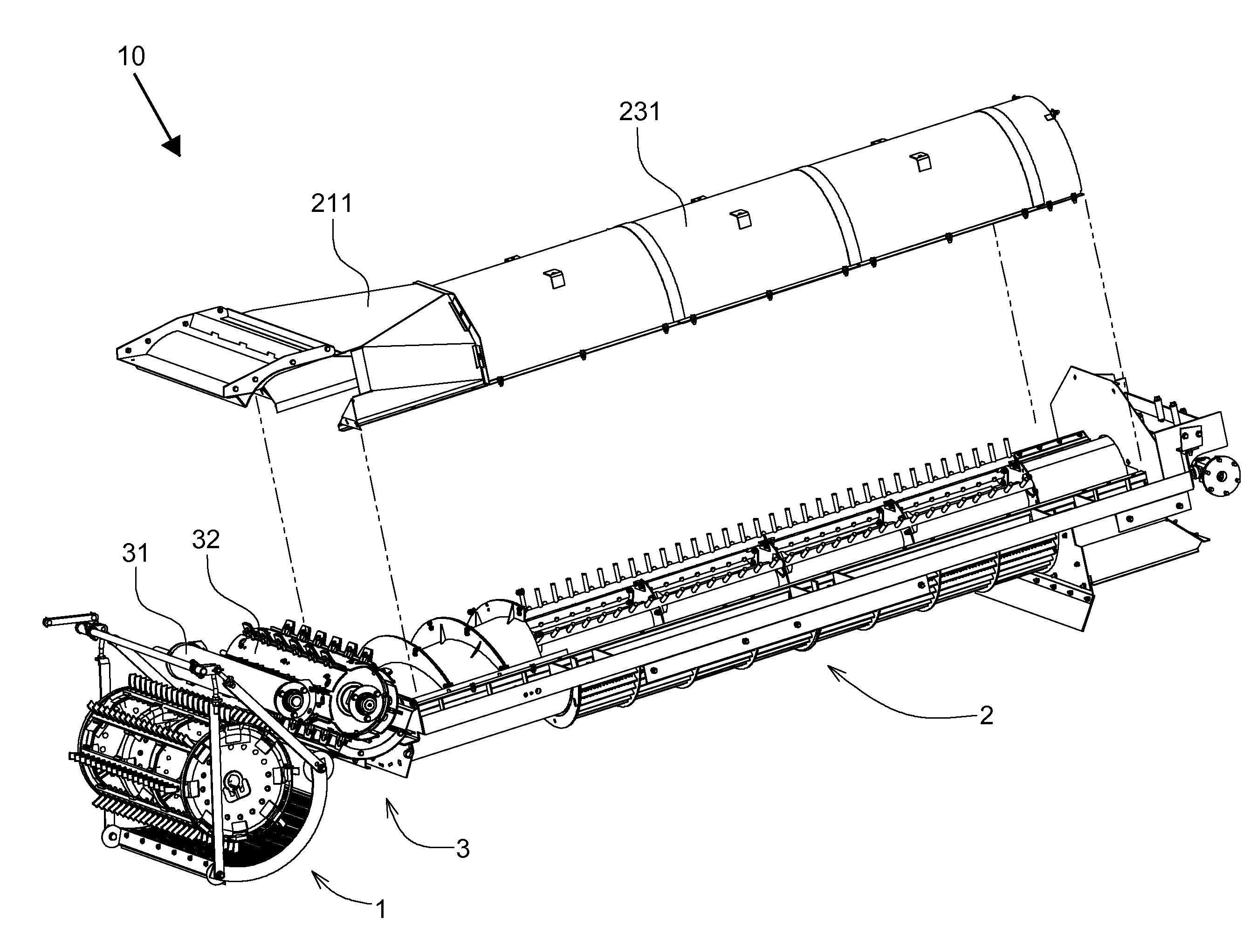
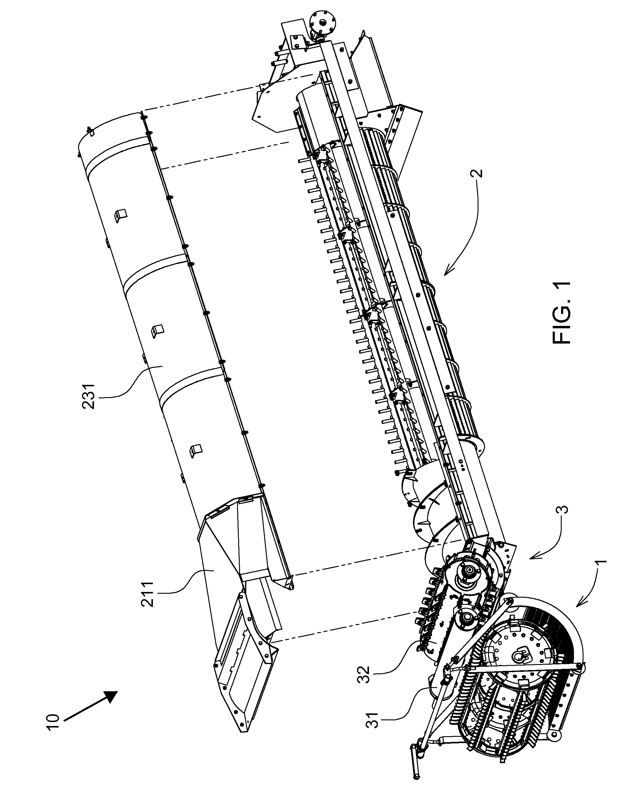
[0022]FIG. 1 shows a threshing and separating device according to the present invention for processing crops which flow through the device in a direction from left to right. For understanding the present invention, the left side of FIG. 1 from which the crops are fed is called as a front side, while the right side of FIG. 1 from which crop stalks are discharged is called as a rear side, and thereby a fore and aft direction is defined. Generally speaking, the front side is a side in a travelling direction of the combine harvester comprising the threshing and separating device.

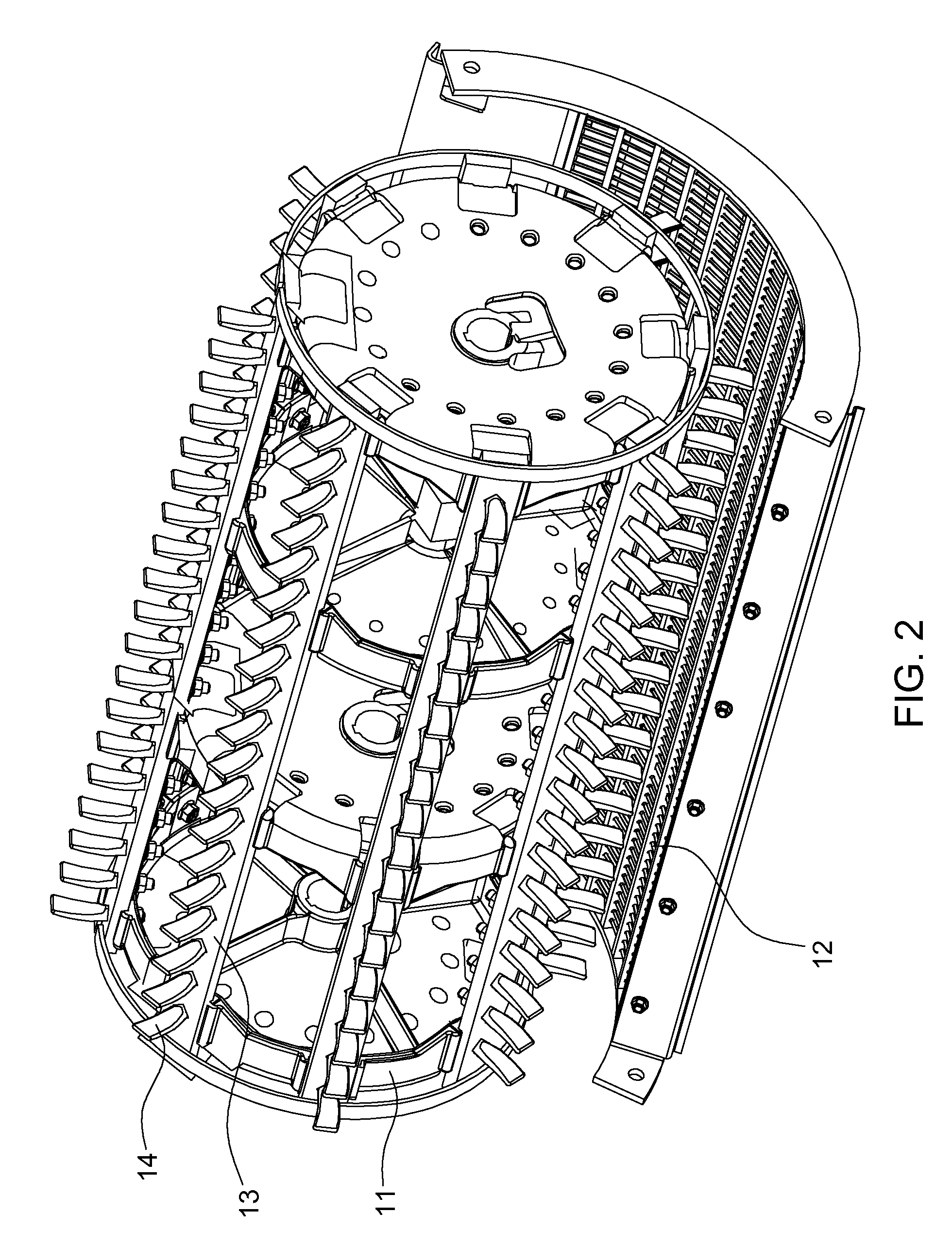
[0023]The threshing and separating device 10 is provided with a first threshing and separating mechanism 1 consisted of a first cylinder 11 and a first concave 12 at its front part, a second threshing and separating mechanism 2 mainly consisted of a second cylinder 20 and a second concave 232 at its rear part, and an intermediate feeding mechanism 3 between the first and second threshing and separating mechanism...

second embodiment

[0034]FIGS. 6 to 11 show the invention. The threshing and separating device 10 is provided with a first threshing (and separating) mechanism 1 comprising a first cylinder 11 and a first concave 12 at its front part, a second threshing and separating mechanism 2 mainly consisted of two second cylinders 20 and two second concaves 232 at its rear part, and an intermediate feeding mechanism 3 between the first and second threshing and separating mechanisms. Crops, after being fed into the threshing and separating device 10, are threshed by the first cylinder, and threshed grains fall through grids of the first concave into a grain collect system which is not shown; then, the crops are fed to the second threshing and separating mechanism 2 by the intermediate feeding mechanism 3, the crops are threshed and grains and stalks are separated from each other along a path in the second threshing and separating mechanism longer than that in the first threshing and separating mechanism, and the ...


PUM


Abstract

A threshing and separating device comprises a first threshing and separating mechanism, a second threshing and separating mechanism, and an intermediate feeding mechanism therebetween. The first threshing and separating mechanism comprises a first cylinder in a form of a toothed rod and a first concave in a form of a wire-grate, and a surface of the first concave facing the first cylinder is provided with no part protruding into a tip circle of threshing teeth of the first cylinder; the second threshing and separating mechanism comprises a second cylinder in a form of a toothed rod and a second concave in a form of a wire-grate, and a surface of the second concave facing the second cylinder is provided with no part protruding into a tip circle of threshing teeth of the second cylinder; the second cylinder comprises a forced feeding portion located at front end thereof and comprising a truncated cone and helical blades on the truncated cone; and a toothed-rod cylinder portion located behind the forced feeding portion and comprising a plurality of second rods parallel to the rotation axis of the second cylinder and uniformly arranged in a circumferential direction thereof, and each second rod is provided with a plurality of second threshing teeth.

Description

CROSS-REFERENCE TO RELATED APPLICATIONS[0001]This application claims the benefit of Chinese Patent Application No. 201410061807.6 filed on Feb. 24, 2014 in the State Intellectual Property Office of China, the whole disclosure of which is incorporated herein by reference.[0002]This application also claims the benefit of Chinese Patent Application No. 201410061976.X filed on Feb. 24, 2014 in the State Intellectual Property Office of China, the whole disclosure of which is incorporated herein by reference.FIELD OF THE INVENTION[0003]The present invention generally relates to a threshing and separating device and a combine harvester comprising the same.BACKGROUND OF THE INVENTION[0004]In a combine harvester, a harvesting device is used to harvest crops, and a threshing and separating device is used to separate grains from the harvested crops. DE 32 14 161 C2 disclosed a threshing and separating device with combined tangential and axial flows. Currently, this kind of threshing and separa...

Claims


Application Information

Patent Timeline
IPC IPC(8): A01F12/46A01F7/04A01D41/12A01F12/24A01F12/39A01D41/02A01F12/22
CPCA01F12/46A01D41/02A01F7/04A01D41/12A01F12/24A01F12/39A01F12/22A01F7/06
Inventor SUEN, BENJAMIN C.ZHUANG, YIBINLI, JUNBANGPANG, FENGBINHAN, YANPENGWANG, HONGYUANPANG, XIUBINGZHEN, BAOHUAN
Owner JOHN DEERE TIANJIN
Learn More