Turbine abradable layer with zig zag groove pattern
a turbine engine and abradable layer technology, applied in machines/engines, liquid fuel engines, mechanical equipment, etc., can solve the problems of local variations in the blade tip gap, reducing the operational reducing the efficiency of the turbine engine, so as to improve engine efficiency performance and reduce the blade tip gap. , the effect of controlling the blade tip gap
- Summary
- Abstract
- Description
- Claims
- Application Information
AI Technical Summary
Benefits of technology
Problems solved by technology
Method used
Image
Examples
embodiment 270
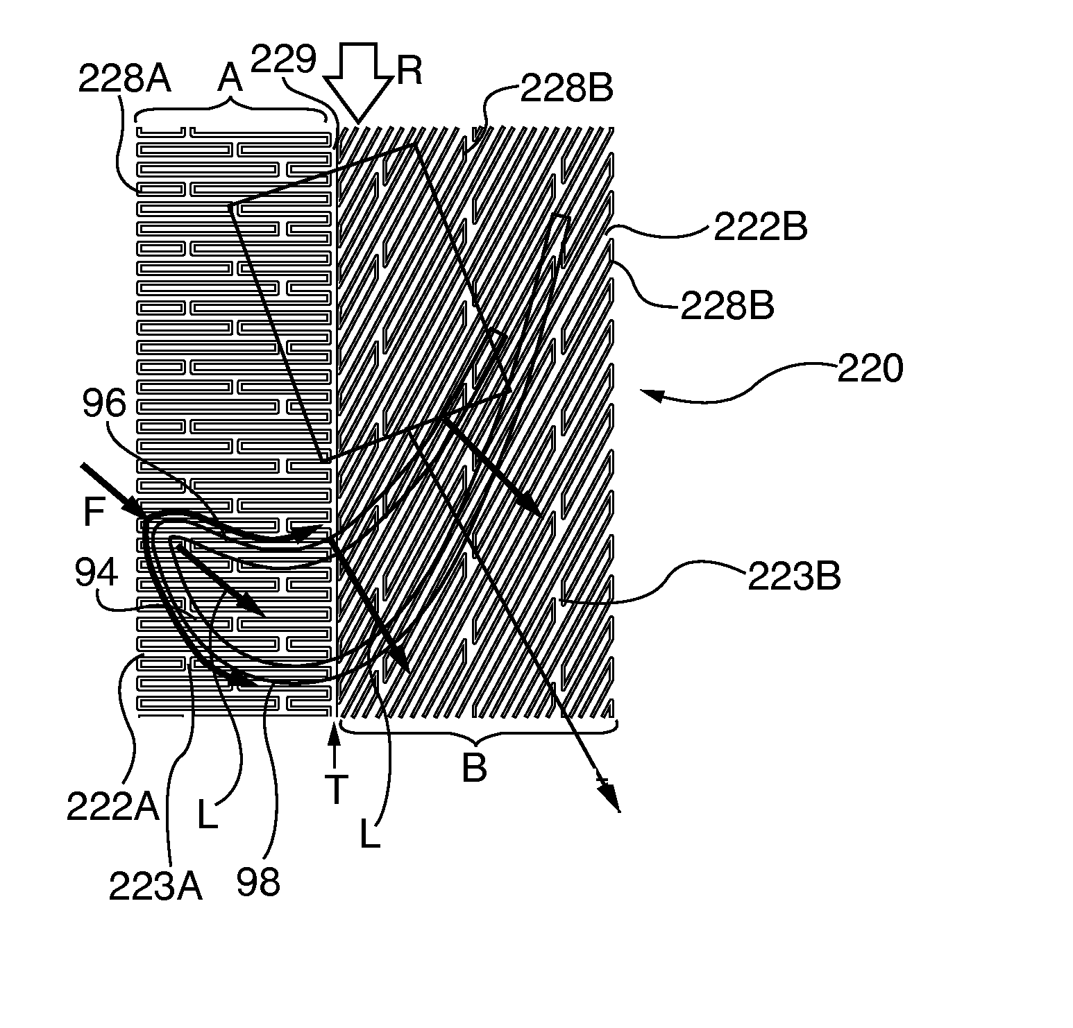
[0117]FIGS. 23-25 show embodiments of abradable component ridge and groove planform arrays that comprise zig-zag patterns. The zig-zag patterns are formed by adding one or more layers of material on an abradable surface substrate to form ridges or by forming grooves within the substrate, such as by known laser or water jet cutting methods. In FIG. 23 the abradable component 250 substrate surface 257 has a continuous groove 258 formed therein, starting at 258′ and terminating at 258″ defines a pattern of alternating finger-like interleaving ridges 252. Other groove and ridge zig-zag patterns may be formed in an abradable component. As shown in the embodiment of FIG. 24 the abradable component 260 has a continuous pattern diagonally oriented groove 268 initiated at 268′ and terminating at 268″ formed in the substrate surface 267, leaving angular oriented ridges 262. In FIG. 25 the abradable component embodiment 270 has a vee or hockey stick-like dual zone multi groove pattern formed b...
embodiment 320
[0126]FIG. 44 shows another stepped profile abradable component 330 with the ridges 332A / B having vertically oriented parallel side walls 335A / B and 336A / B. The lower ridge terminates in ridge plateau 334B, upon which the upper ridge 332A is oriented and terminates in ridge tip 334A. In some applications it may be desirable to employ the vertically oriented sidewalls and flat tips / plateaus that define sharp-cornered profiles, for airflow control in the blade tip gap. The upper wear zone I is between the ridge tip 334A and the ridge plateau 334B and the lower wear zone is between the plateau and the abradable surface 337. As with the abradable embodiment 320 of FIG. 43, while the ridges and grooves shown in FIG. 44 are symmetrically spaced, other spacing profiles may be chosen, including different ridge cross sectional profiles that create the stepped wear zones I and II.
[0127]In another permutation or species of stepped ridge construction abradable components, separate upper and low...
embodiment 350
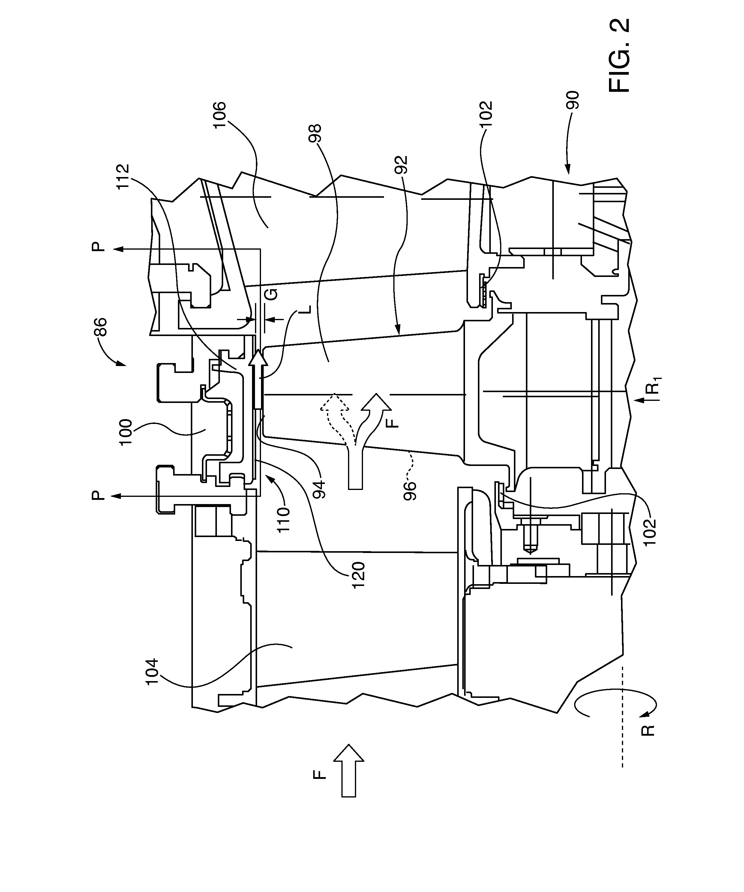
[0128]As shown in FIG. 46, in certain turbine applications it may be desirable to control blade tip leakage by employing an abradable component 350 embodiment having asymmetric profile abradable ridges 352 with vertically oriented, sharp-edged upstream sidewalls 356 and sloping opposite downstream sidewalls 355 extending from the substrate surface 357 and terminating in ridge tips 354. Blade leakage L is initially opposed by the vertical sidewall 356. Some leakage airflow L nonetheless is compressed between the ridge tip 354 and the opposing blade tip 94 while flowing from the high pressure blade side 96 to the lower pressure suction blade side 98 of the blade. That leakage flow follows the downward sloping ridge wall 355, where it is redirected opposite blade rotation direction R by the vertical sidewall 356 of the next downstream ridge. The now counter flowing leakage air L opposes further incoming leakage airflow L in the direction of blade rotation R. Dimensional references show...
PUM
| Property | Measurement | Unit |
|---|---|---|
| Angle | aaaaa | aaaaa |
| Pressure | aaaaa | aaaaa |
| Width | aaaaa | aaaaa |
Abstract
Description
Claims
Application Information
 - R&D
- Intellectual Property
- Life Sciences
- Materials
- Tech Scout
- Unparalleled Data Quality
- Higher Quality Content
- 60% Fewer Hallucinations
Browse by: Latest US Patents, China's latest patents, Technical Efficacy Thesaurus, Application Domain, Technology Topic, Popular Technical Reports.
© 2025 PatSnap. All rights reserved.Legal|Privacy policy|Modern Slavery Act Transparency Statement|Sitemap|About US| Contact US: help@patsnap.com


