Suction Cup with Flat Framework

a suction cup and flat framework technology, applied in the field of suction cups, can solve the problems of reduced and insufficient adsorptive force, high production cost, and difficult operation, and achieve the effects of large adsorptive force, effective transfer of pressing force, and simple structur

Active Publication Date: 2015-08-27
ZHONGSHAN TAILI HOUSEHOLD PROD MFG
View PDF35 Cites 20 Cited by
  • Summary
  • Abstract
  • Description
  • Claims
  • Application Information

AI Technical Summary

Benefits of technology

[0007]An object of this invention is to provide a type of suction cup with a flat framework that has a simple structure, can effectively transfer pressing forces, has a large adsorptive force, and does not easily fall off from the supporting surface.

Problems solved by technology

However, such suction cup cannot fully discharge air between the cup's adsorption surface and the supporting surface, and air may easily seep in via the edge of the adsorption surface, the adsorptive force is thus reduced and insufficient.
However, this type of suction cup has a complicated structure and high production cost, it is not easy to operate, and its adsorptive force is not strong.
However, adsorptive force of existing suction cup with flat framework is not large enough, so that the suction cup easily falls from the wall surface, in particular when conditions of the wall surface are not ideal (for example, the wall surface is too smooth or has sags and crests), the friction force between the suction cup and the wall surface is too small, resulting in falling off of the suction cup.
Thus, it cannot meet the need in terms of handing capacity and durability.

Method used


Image

  • Suction Cup with Flat Framework
  • Suction Cup with Flat Framework
  • Suction Cup with Flat Framework

Examples


embodiment 1

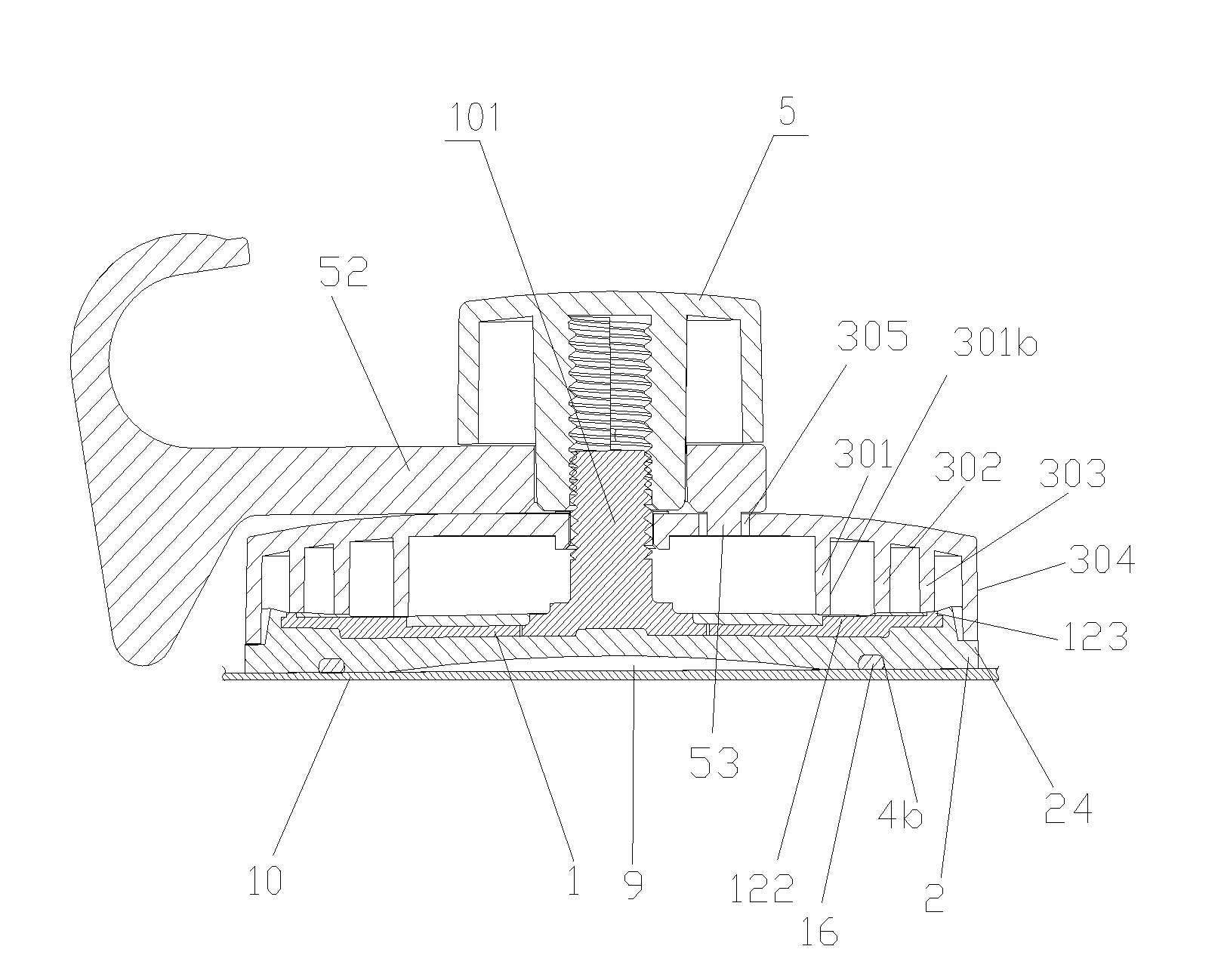
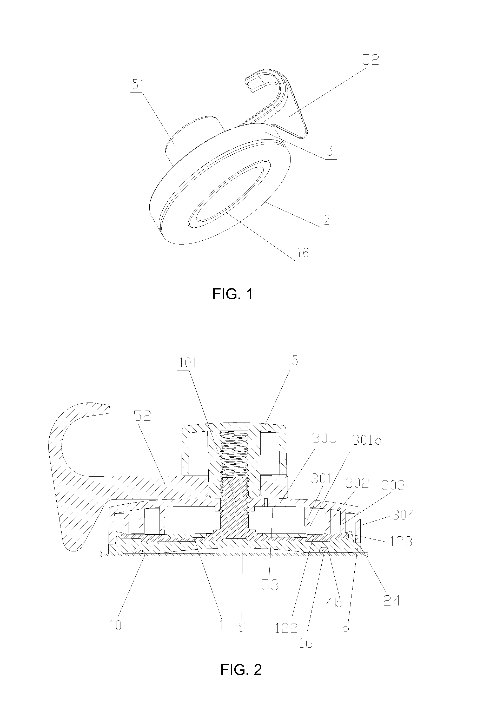
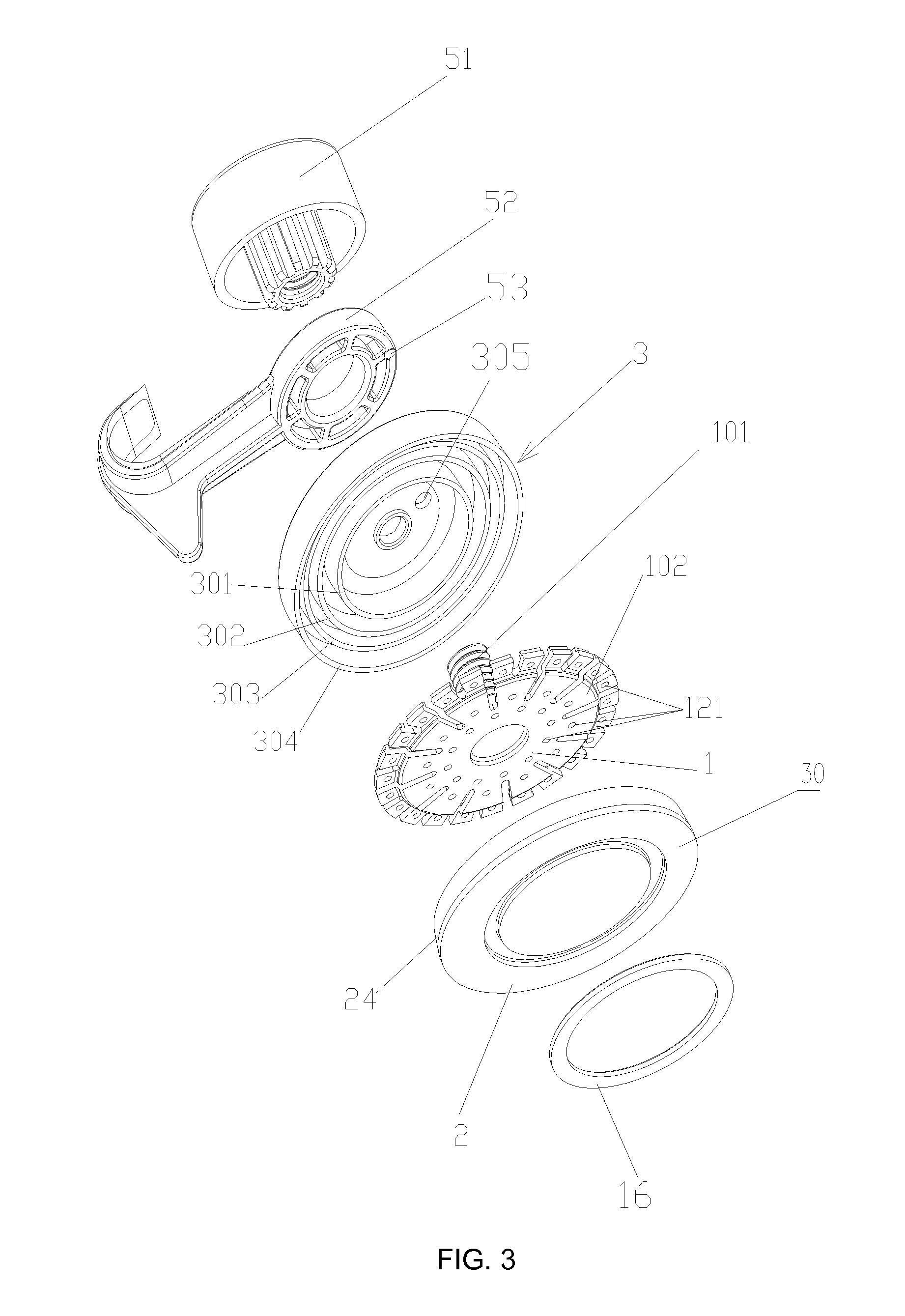
[0058]Shown in FIG. 1-FIG. 4, is a type of suction cup with a flat framework disclosed of the present invention, comprising a flat framework 1, a cup body 2 covering framework 1, a connecting rod 101 provided on the back surface of framework 1 and passing through cup body 2, a hat-shaped suction cup cover 3 put on this connecting rod 101 and covering the back surface of cup body 2, and a pressing element provided on back surface of cup cover 3 and connected to the connection rod 101; wherein seal elements are provided on adsorption surface of suction cup body 2 and protruding rings are provided on inner surface of suction cup cover 3 used to touch and press the back surface of cup body 2 at the area corresponding to the seal elements. Framework 1 extends from the center to near the edge of cup body 2. Annular protruding ribs are provided on the circumference of the back surface of framework 1, extending into through holes provided on the back surface of cup body 2 so that the annula...

embodiment 2

[0064]As shown in FIG. 5-3, FIG. 5-4, and FIG. 9-FIG. 12, the difference between embodiment 2 and embodiment 1 is described as follows: inner protruding ring 302 comprises radial protruding ribs distributed on a circumference enclosing central protruding ring 301, with these radial protruding ribs extending from central protruding ring 301 to outer protruding ring 303. Central protruding ring 301 is higher than outer protruding ring 303 and the top surface of radial protruding ribs inclines from central protruding ring 301 toward outer protruding ring 303.

embodiment 3

[0065]As shown in FIG. 5, FIG. 5-1, and FIG. 5-2, the difference between embodiment 3 and embodiment 2 is described as follows: the sealing element is a sealing gasket 21 at the center of cup body 2's adsorption surface, with a contact friction surface 30 formed between sealing gasket 21 and the edge of the cup body. With the suction cup closely attached to the supporting surface, outer ring surface 301b of central protruding ring 301 on suction cup cover is at inner side of sealing gasket 21 outer side 4ba.


PUM


Abstract

A suction cup, including a flat framework, a suction cup body covering the framework, a connection rod disposed on the back surface of the framework and passing through the cup body, a cup cover covering the connection rod and the cup body, and a pressing element provided on the back surface of the cup cover and in connection with the connection rod, a seal element on the adsorption surface of the cup body, and an annular protruding ring on the inner surface of the cup cover at a location corresponding to the seal element for touch pressing the inner surface of the cup body against the seal element. The invention uses rigid force transfer, and thus the force transfer is more effective. The sealing element enhances the airtightness of the suction cavity and increases the absorption force of the suction cup. When pulling the connection rod, due to the existence of the sealing element, the air cannot easily enter the suction cavity, and because before the pulling the framework is in a flat state, it can produces a high degree of vacuum and thus adsorption force so that the suction cup will not fall off the supporting surface easily. Furthermore, the suction cup of the invention is structurally simple with a lower manufacturing cost.

Description

FIELD OF THE INVENTION[0001]This invention relates to a type of suction cup for civilian use, in particular a type of suction cup with a flat framework.BACKGROUND OF THE INVENTION[0002]Suction cups for civilian use are mainly for people to hang articles on a supporting surface such as walls. As it can be relocated to any positions at will, it can be conveniently used to hang towels, clothing articles, etc. Such suction cup is easy to use and can maintain attachment via vacuum assisted by adhesion, without drilling on the wall, it has therefore been widely used.[0003]Existing suction cups may be made with or without a framework. Traditional suction cup without a framework is normally made of soft plastic integrally formed by injection molding. However, such suction cup cannot fully discharge air between the cup's adsorption surface and the supporting surface, and air may easily seep in via the edge of the adsorption surface, the adsorptive force is thus reduced and insufficient. The ...

Claims


Application Information

Patent Timeline
Patent Type & Authority Applications(United States)
IPC IPC(8): F16B47/00F16M13/02
CPCF16M13/022F16B47/00F16B47/006
Inventor SHI, ZHENGBING
Owner ZHONGSHAN TAILI HOUSEHOLD PROD MFG
Why Eureka
Try Eureka