Rotorcraft with integrated light pipe support members

a technology of light pipe support and rotorcraft, which is applied in the direction of lighting support devices, electric apparatus casings/cabinets/drawers, landing aids, etc., can solve the problems of reducing the response time of a user to correct course, difficult to adequately address design considerations, and difficulty in operation of radio controlled model rotorcraft, etc., to improve the ease of flight and flight performance, increase structural stability, and increase the visibility of the rotorcra

Active Publication Date: 2015-08-27
TRAXXAS
View PDF12 Cites 9 Cited by
  • Summary
  • Abstract
  • Description
  • Claims
  • Application Information

AI Technical Summary

Benefits of technology

[0011]Provided is an radio controlled model rotorcraft implemented with features improving ease of flight and flight performance by increasing structural stability, increasing rotorcraft visibility and orientation awareness through the use of multifunctioning, configurable, and aesthetically pleasing components, while also increasing resistance to damage from crashes through use of impact and vibration absorbing components.

Problems solved by technology

Several characteristics inherent to radio controlled model rotorcraft operation and appearance add to the difficulty in adequately addressing these design considerations.
Radio controlled model rotorcraft are difficult to operate for several reasons.
Additionally, radio controlled model rotorcraft are capable of reaching incredible speeds during flight, such as when descending from high altitude, reducing the response time for a user to correct course to avoid a crash.
Users may also have difficulty discerning the orientation of the radio controlled model rotorcraft during flight, especially while performing aerial tricks or when operating a rotorcraft that has several propellers, causing the radio controlled model rotorcraft to have a similar appearance from all sides.
Confusion as to the orientation of the radio controlled model rotorcraft during flight greatly increases the likelihood of a loss of control by the user and a subsequent crash.
For flying vehicles weight increases are undesirable, however, since weight increases degrade performance.
Further, weight increase may result in increased cost if higher power or additional thrust-generating components are used to compensate for the additional weight.

Method used


Image

  • Rotorcraft with integrated light pipe support members
  • Rotorcraft with integrated light pipe support members
  • Rotorcraft with integrated light pipe support members

Examples


Embodiment Construction

[0029]In the following discussion, numerous specific details are set forth to provide a thorough understanding of the present invention. However, those skilled in the art will appreciate that the present invention may be practiced without such specific details. In other instances, well-known elements have been illustrated in schematic or block diagram form in order not to obscure the present invention in unnecessary detail. Additionally, and for the most part, details concerning well-known features and elements have been omitted inasmuch as such details are not considered necessary to obtain a complete understanding of the present invention, and are considered to be within the understanding of persons of ordinary skill in the relevant art. Additional details are shown in the Appendix attached hereto and incorporated by reference for all purposes.

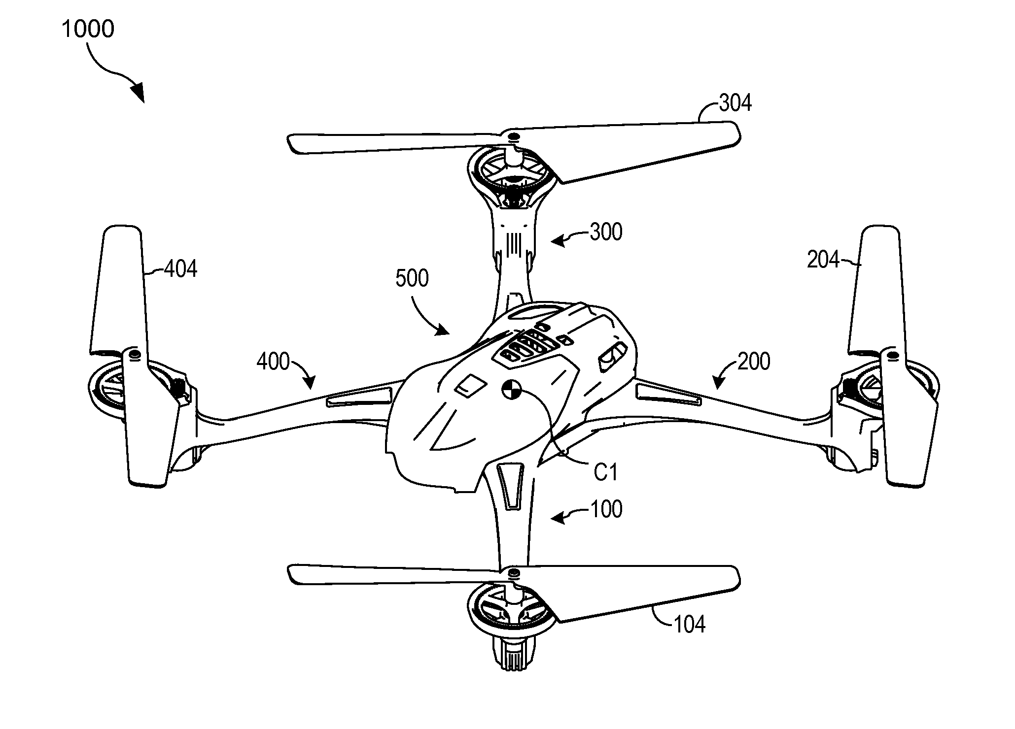
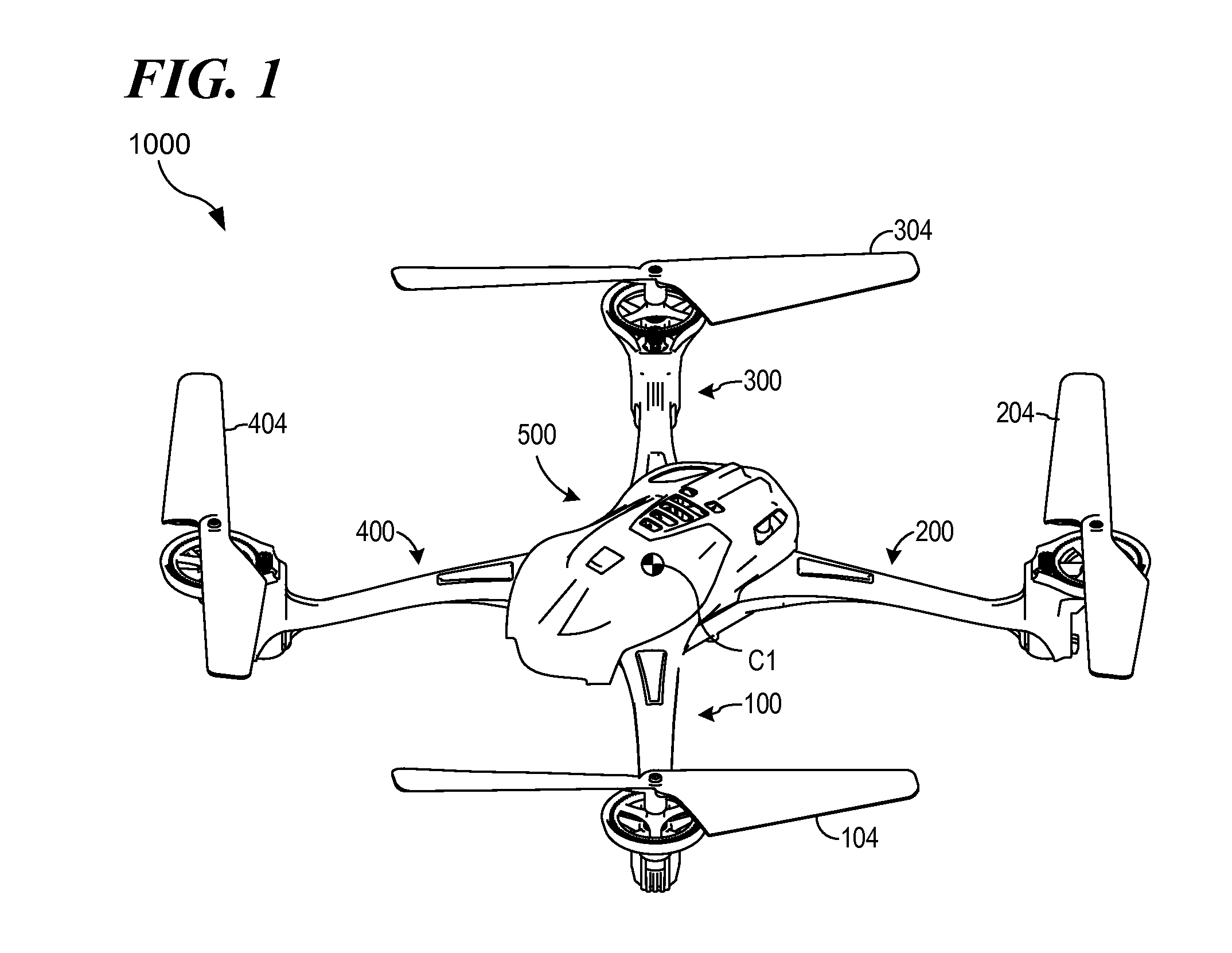
[0030]Referring first to FIG. 1, a particular embodiment of a radio controlled model rotorcraft, a rotorcraft 1000, is shown. According to ...


PUM


Abstract

A radio controlled model rotorcraft implemented with features improving ease of flight and flight performance by increasing structural stability, increasing rotorcraft visibility and orientation awareness through the use of multifunctioning, configurable, and aesthetically pleasing components, while also increasing resistance to damage from crashes through use of impact and vibration absorbing components.

Description

CROSS-REFERENCE TO RELATED APPLICATIONS[0001]This application is a division of, and claims the benefit of the filing date of, co-pending U.S. patent application Ser. No. 14 / 461,228 entitled ROTORCRAFT WITH INTEGRATED LIGHT PIPE SUPPORT MEMBERS, filed Aug. 15, 2014, which claims the benefit of the filing date of, co-pending U.S. provisional patent application Ser. No. 61 / 866,530 entitled QUADCOPTER WITH INTEGRATED LIGHT PIPE SUPPORT MEMBERS, filed Aug. 15, 2013, the entire contents of which are incorporated herein by reference for all purposes.BACKGROUND OF THE INVENTION[0002]1. Field of the Invention[0003]The present invention relates to radio controlled model rotorcrafts, and, more particularly, to means and methods of assembling and retaining components of radio controlled model rotorcraft while enhancing aesthetically pleasing aspects of a rotorcraft.[0004]2. Description of the Related Art[0005]Radio controlled model rotorcrafts are propeller driven remote controlled vehicles con...

Claims


Application Information

Patent Timeline
Patent Type & Authority Applications(United States)
IPC IPC(8): H05K5/03H05K1/18F21V33/00B64C39/02
CPCB64C39/024A63H27/12A63H17/28B64C2201/027B64U10/13B64U30/20B64C27/32
Inventor CHRISTENSEN, CASEY CHRISTEN JENSALLMENDINGER, OTTO KARLHOHNHOLT, RICHARD DOUGLASPOTEET, KENTSCHMITZ, SCOTT ROLLIN MICHAELBLACKWELL, THOMAS
Owner TRAXXAS
Why Eureka
Try Eureka