Jaw repositioning appliance

a repositioning and jaw technology, applied in the field of jaw repositioning appliances, can solve the problems of prolonged load on patients, inability to fully function in vertical direction control, and long time-consuming for jaw repositioning to be corrected

a repositioning and jaw technology, applied in the field of jaw repositioning appliances, can solve the problems of prolonged load on patients, inability to fully function in vertical direction control, and long time-consuming for jaw repositioning to be corrected

US20150245888A1Inactive Publication Date: 2015-09-03HASEGAWA SHIN +2

Image

  • Jaw repositioning appliance
  • Jaw repositioning appliance
  • Jaw repositioning appliance

Examples


Embodiment Construction

[0027]Hereinafter, embodiments of the present invention will be explained based on the drawings. In the following explanation, expressions about an up-and-down direction, a front-and-rear direction and a left-and-right direction are used. These directions are used to express positional relationships centering on a patient who uses a jaw repositioning appliance of the present invention.

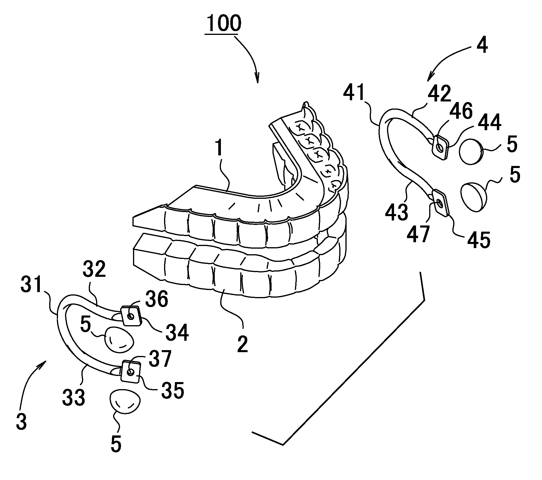
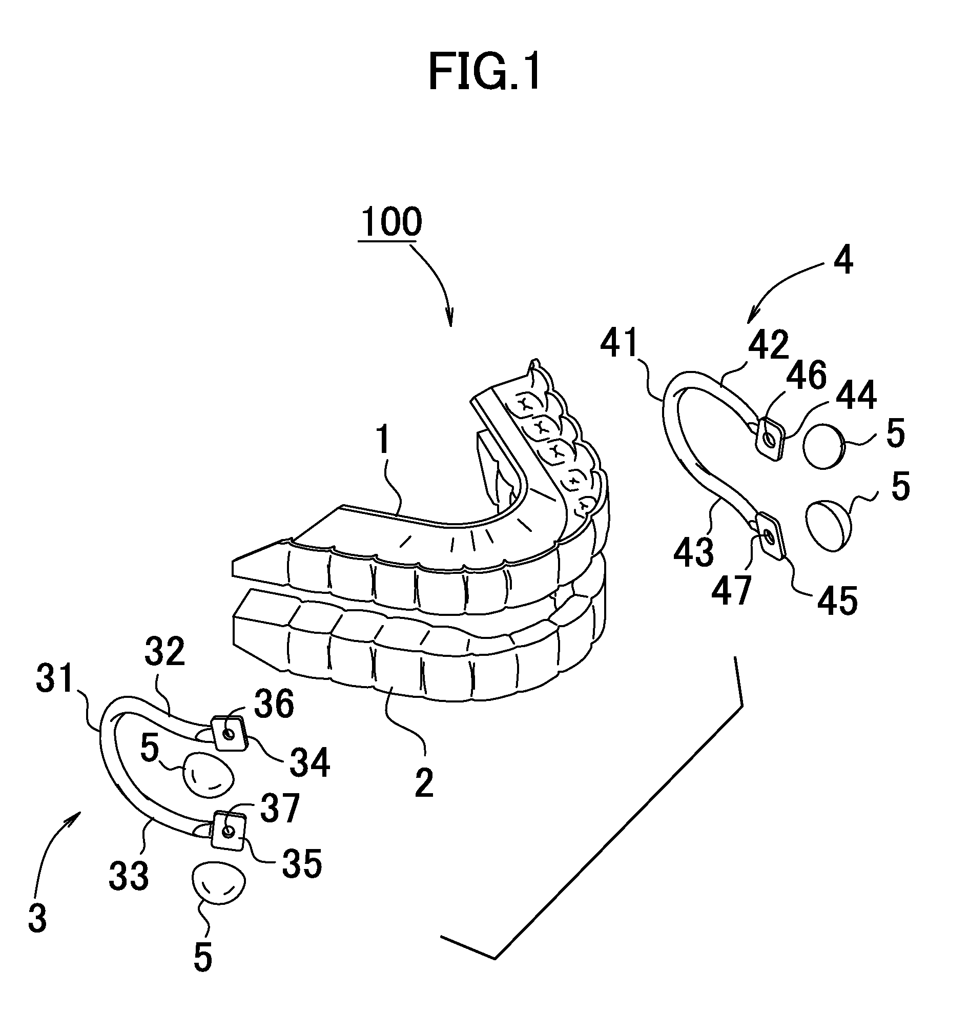
[0028]FIG. 1 is a view showing a first embodiment of the present invention. As shown in the drawing, a jaw repositioning appliance 100 according to the present embodiment is constituted with a maxillary plate 1, a mandibular plate 2 and a pair of left and right connecting wires 3, 4. The maxillary plate 1 and the mandibular plate 2 are manufactured in accordance with dentition of the patient. A general-purpose synthetic resin used as engineering plastics such as polycarbonate is used as a material of the maxillary plate 1 and the mandibular plate 2. The connecting wires 3, 4 are arranged symmetrically ...


PUM


Abstract

A jaw repositioning appliance has a maxillary plate fit to a maxilla, a mandibular plate fit to a mandible, and at least one connecting wire constituted with a wire rod, which has the Young's modulus of 100 GPa or lower, which has tensile strength value of 0.01 or higher with respect to the Young's modulus, and which can deform elastically. The connecting wire has at least one curved portion. One end (34, 44) of the connecting wire is attached to the maxillary plate and the other end of the connecting wire is attached to the mandibular plate.

Description

TECHNICAL FIELD[0001]The present invention relates to a jaw repositioning appliance and in particular relates to a removable orthodontic appliance used for correcting a position of a mandible with respect to a maxilla to a normal state.BACKGROUND ART[0002]Generally, orthodontic treatment is performed in treatment for malocclusion. The malocclusion includes a case where an abnormality exists in the shape of a dental arch as represented by crowding of teeth and also a case where an abnormality exists in a relationship between the dental arches of the maxilla and the mandible, for instance. In the treatment of the crowding and the like, an appliance called a multi-bracket appliance is fit to surfaces of teeth, whereby the shape of the dental arch is corrected by pressing or pulling the teeth. In the treatment for the case where there is an abnormality in a jaw positional relationship, a jaw repositioning appliance is used. The jaw repositioning appliance includes a form fit to on an ou...

Claims


Application Information

Patent Timeline
03 Sep 2015
Publication
US20150245888A1
IPC
A61C7/36; A61C7/08
CPC
A61C7/08; A61C7/36
Inventors
HASEGAWA, SHIN