Liquid jet head and liquid jet apparatus

Active Publication Date: 2015-09-10
SII PRINTEK
View PDF3 Cites 0 Cited by
  • Summary
  • Abstract
  • Description
  • Claims
  • Application Information

AI Technical Summary

Benefits of technology

The invention is about a new method for making an electrode in a jet channel used for recording. The method ensures that the electrodes are easily separated and do not touch the bottom of the channel, which is important for high-density recording. The method also allows for faster deposition of the conductive material and higher productivity, even when the groove width is narrowed. Overall, the method improves the efficiency and productivity of the jet channel.

Problems solved by technology

Therefore, manufacturing process steps become complicated and the number of man-hour is increased.
The oblique vapor deposition method requires a longer time to deposit the conductive material in the depth direction of the wall surface as the groove width becomes narrower, and productivity is reduced.

Method used


Image

  • Liquid jet head and liquid jet apparatus
  • Liquid jet head and liquid jet apparatus
  • Liquid jet head and liquid jet apparatus

Examples


first embodiment

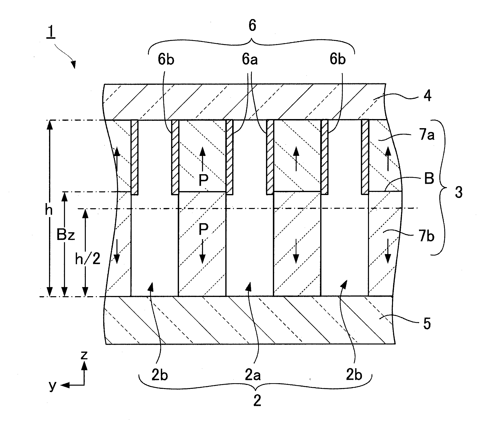
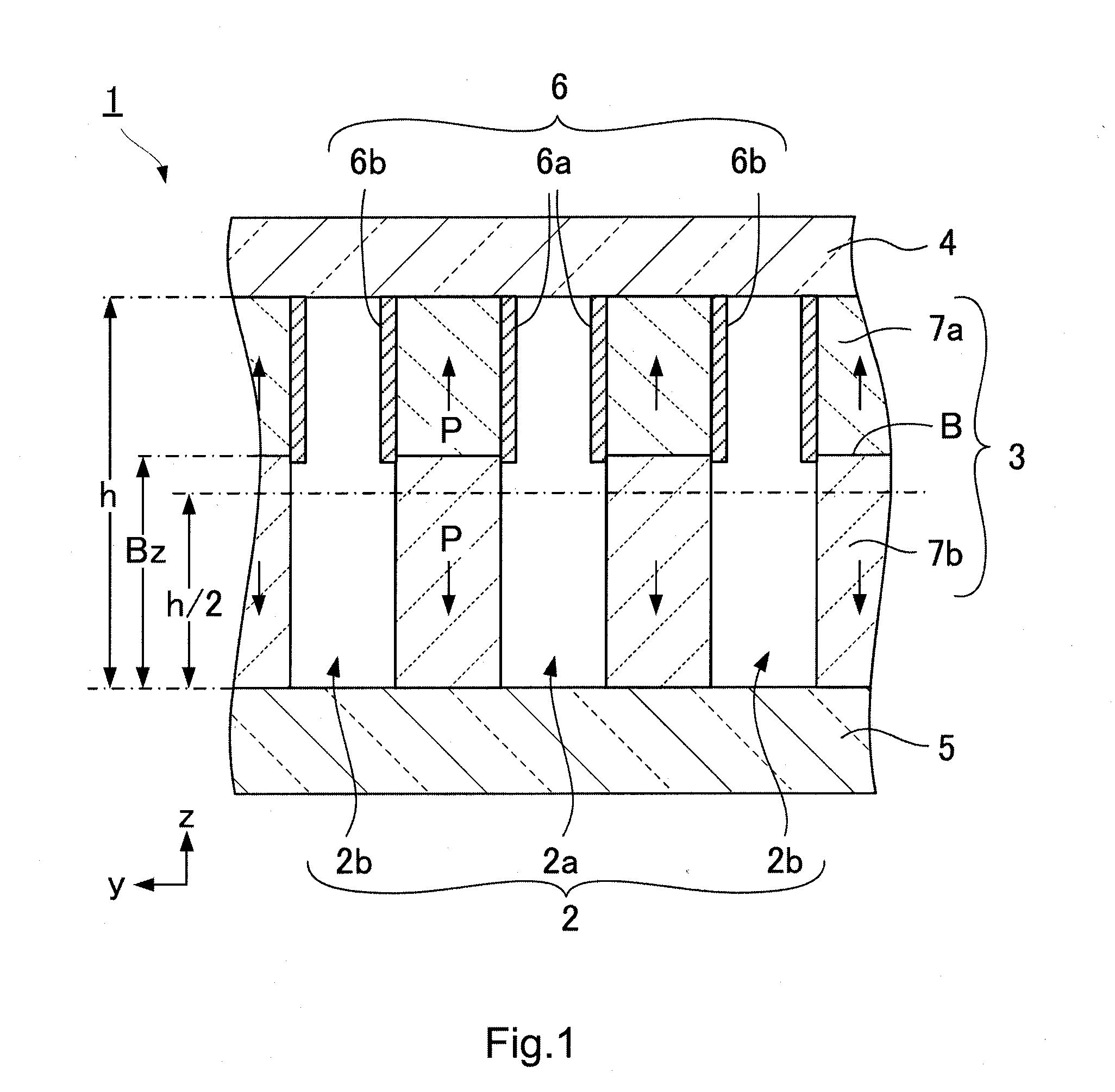
[0026]FIG. 1 is a schematic cross-sectional view of channels applied to a liquid jet head 1 according to a first embodiment of the present invention. The first embodiment represents a basic configuration of the present invention. As illustrated in FIG. 1, the liquid jet head 1 includes a channel 2, a side wall 3 made of a piezoelectric material and arranged between the channels 2, an upper member 4 fixed to an upper end of the side wall 3 and installed on an upper portion of the channel 2, a lower member 5 fixed to a lower end of the side wall 3 and installed on a lower portion of the channel 2, and an electrode 6 installed on a wall surface of the side wall 3. The side wall 3 has two piezoelectric materials having mutually different polarization directions and laminated in a height direction (z direction), interposing a polarization boundary B. A height Bz of the polarization boundary B is positioned above h / 2 of a height h of the side wall 3. The electrode 6 is installed from an u...

second embodiment

[0036]FIGS. 3A and 3B are explanatory diagrams of a liquid jet head 1 according to a second embodiment of the present invention. FIG. 3A is a schematic exploded perspective view of the liquid jet head 1, and FIG. 3B is a schematic cross-sectional view of an ejection channel 2a along a longitudinal direction (x direction). The liquid jet head 1 is an edge shoot-type liquid jet head. The same portions or portions having the same function are denoted with the same reference sign.

[0037]As illustrated in FIGS. 3A and 3B, the liquid jet head 1 includes a piezoelectric body substrate 7, a cover plate 9 installed on an upper surface UP of the piezoelectric body substrate 7, and a nozzle plate 8 installed at an end surface of one side of the piezoelectric body substrate 7. The ejection channel 2a and a non-ejection channel 2b, which are narrow and long in an x direction, are alternately formed in a y direction in the piezoelectric body substrate 7. A side wall 3 is installed between the ejec...

third embodiment

[0043]FIGS. 4A and 4B are explanatory diagrams of a liquid jet head 1 according to a third embodiment of the present invention. FIG. 4A is a schematic exploded perspective view of the liquid jet head 1, and FIG. 4B is a schematic cross-sectional view of an ejection channel 2a along a longitudinal direction (x direction). The liquid jet head 1 is a side shoot-type liquid jet head. The same portions or portions having the same function are denoted with the same reference sign.

[0044]As illustrated in FIGS. 4A and 4B, the liquid jet head 1 includes a piezoelectric body substrate 7, a nozzle plate 8 installed on an upper surface UP of the piezoelectric body substrate 7, and a cover plate 9 installed on a lower surface LP of the piezoelectric body substrate 7. The ejection channel 2a and a non-ejection channel 2b, which are long and narrow in the x direction, are alternately formed in a y direction in the piezoelectric body substrate 7. A side wall 3 is installed between the ejection chan...


PUM


Abstract

A liquid jet head includes a side wall installed between channels, and in which two piezoelectric materials having mutually different polarization directions are laminated in a height direction, interposing a polarization boundary, an upper member fixed to an upper end of the side wall and installed on an upper portion of the channel, a lower member fixed to a lower end of the side wall and installed on a lower portion of the channel, and an electrode installed on a wall surface of the side wall, wherein the polarization boundary is positioned above ½ the height of the side wall, and the electrode is installed from an upper end of the wall surface, to a vicinity of the polarization boundary, or below the polarization boundary and above a lower end of the wall surface.

Description

BACKGROUND[0001]1. Technical Field[0002]The present invention relates to a liquid jet head and a liquid jet apparatus that jet and record liquid droplets on a recording medium.[0003]2. Related Art[0004]In recent years, liquid jet heads in an ink jet system have been used, which eject ink droplets on a recording paper or the like to record characters and figures, or eject a liquid material on a surface of an element substrate to form a functional thin film. This system introduces a liquid such as an ink or a liquid material from a liquid tank to a channel through a supply tube, applies a pressure to the liquid filled in the channel, and ejects the liquid through a nozzle that communicates with the channel, as liquid droplets. In ejecting the liquid droplets, this system moves the liquid jet head and / or the recording medium to record the characters and figures or to form a functional thin film or a three-dimensional structure having a predetermined shape.[0005]FIG. 6 is a schematic cr...

Claims


Application Information

Patent Timeline
IPC IPC(8): B41J2/14
CPCB41J2/14209B41J2/14201B41J2002/14491
Inventor DOMAE, YOSHINORI
Owner SII PRINTEK
Why Eureka
Try Eureka