Roller blind system for a sliding roof

Inactive Publication Date: 2015-09-10
ROOF SYST GERMANY
View PDF8 Cites 2 Cited by
  • Summary
  • Abstract
  • Description
  • Claims
  • Application Information

AI Technical Summary

Benefits of technology

[0027]Furthermore, it can be provided that the friction element is a pivotally mounted friction piece. This is a simple construction easy to realize, which operates reliably. Here as well, the movement in opening direction can urge the friction piece against a wall such that an additional frictional force is produced in that the friction piece is braced or tightened so to speak between wall and guide rail. A movement in closing direction leads to a rotation or pivotal movement of the friction piece, so that the friction piece without stop only slides across the wall and no high frictional force can be produced any more. The friction element also can be an expanding spring. During a movement in opening d

Problems solved by technology

This is undesired for example acc

Method used


Image

  • Roller blind system for a sliding roof
  • Roller blind system for a sliding roof
  • Roller blind system for a sliding roof

Examples


first embodiment

[0049]FIGS. 5 and 6 show a roller blind system according to the invention with a device 26 for increasing the opening force of the roller blind system.

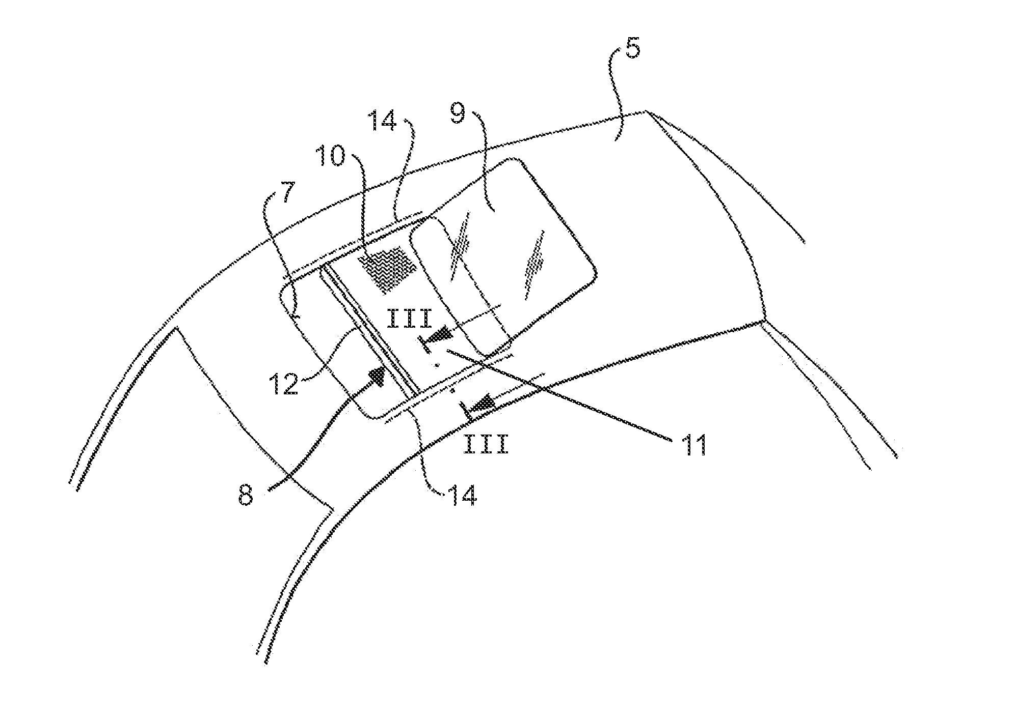
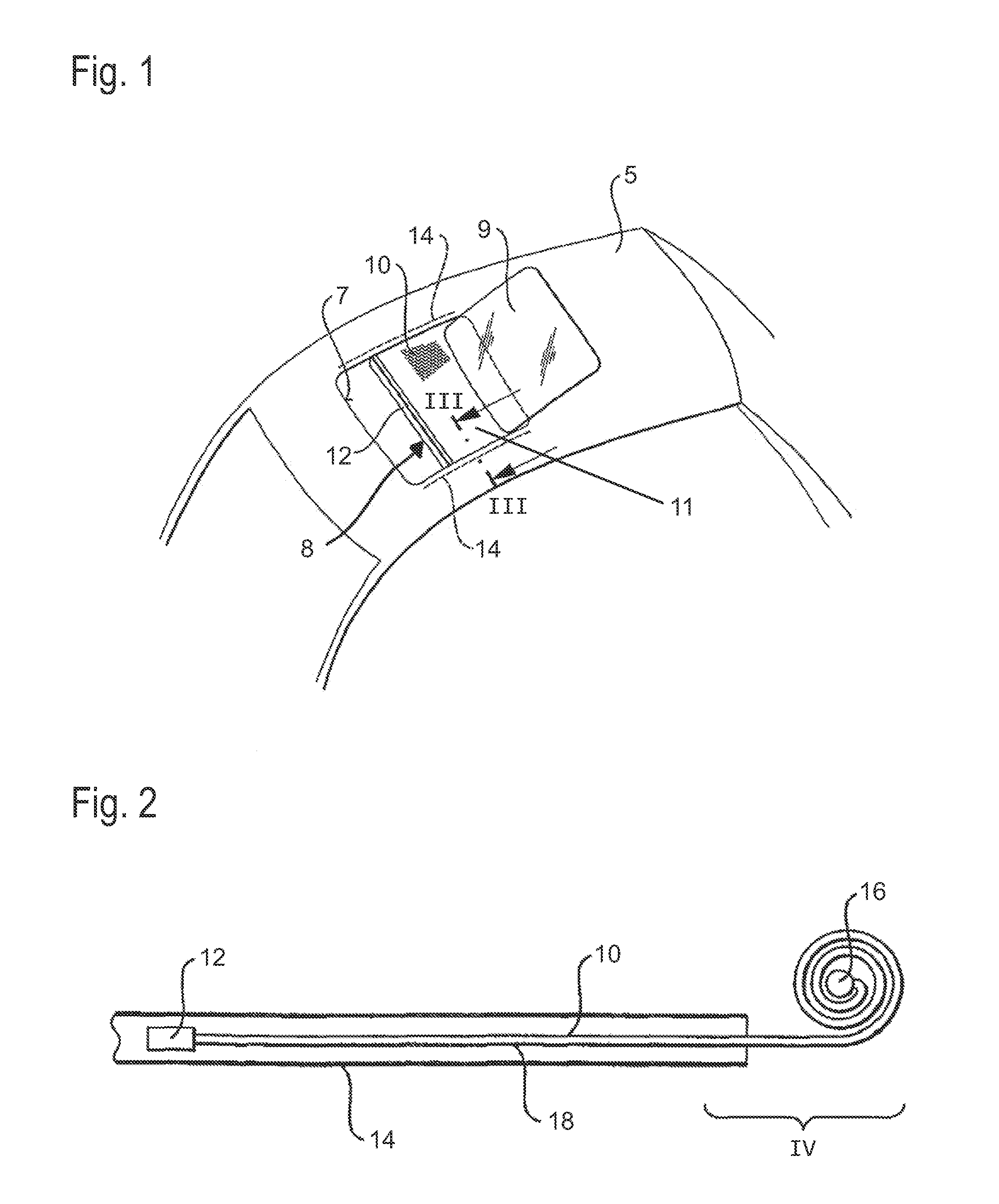
[0050]At the lateral ends of the crossrail 12 a slider 28 each is located, which is guided in the guide rail 14, so that the crossrail 12 is shiftable via its sliders 28.

[0051]The slider 28 includes a device 26 for increasing the opening force, which comprises a wedge guide 30 and a friction wedge 32 which is guided in the wedge guide 30. The friction wedge 32 also slides along a wall of the guide rail 14, preferably along the central web of the guide rail 14. Optionally, the slider 28 itself cannot at all contact the central web shown in FIG. 5 or even the guide rail 14, so that the friction wedge 32 alone makes contact with the guide rail.

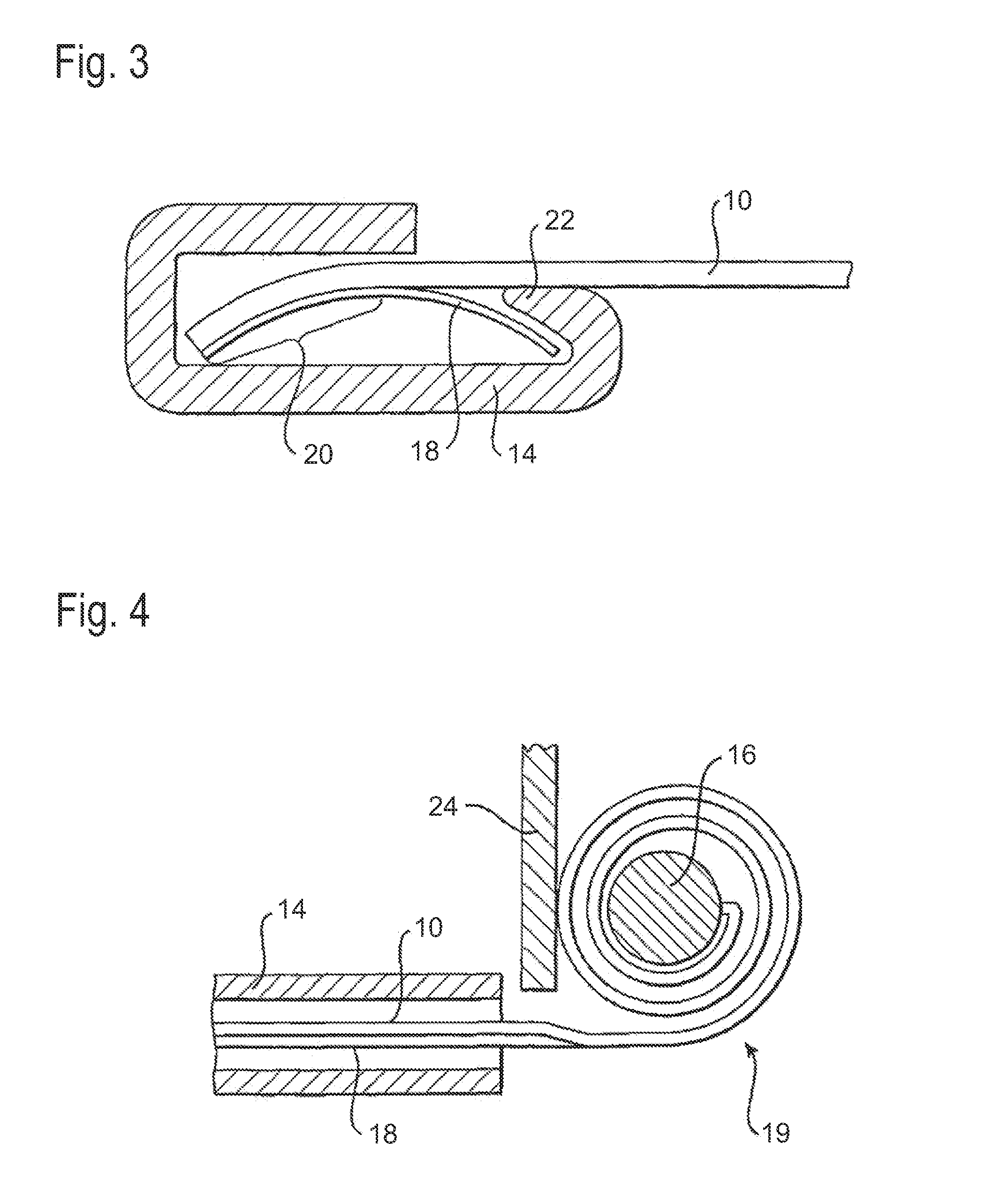
[0052]At its end facing away from the coil (cf. FIG. 4), the wedge guide 30 has a smaller height than at its end facing the coil. The friction wedge 32 correspondingly is inserted into the wedge gu...

second embodiment

[0060]FIGS. 7 and 8 show a roller blind system according to the invention with a device 26 for increasing the opening force.

[0061]The roller blind system and the device 26 for increasing the opening force substantially are identical with the roller blind system described in FIGS. 1 to 6 with the exception of the following differences:

[0062]Instead of a friction wedge 32, the device 26 for increasing the opening force includes a friction piece 34 which is pivotally mounted on a pin 38 in a friction piece guide 36 provided in the slider 28.

[0063]The friction piece 34 is partly elastic and includes a sleeve or a friction layer of silicone material.

[0064]The friction piece 34 has a braking surface 40 and a sliding surface 42, e.g. in the form of a chamfer 42.

[0065]The sliding surface 42 for example is a surface adjacent to or adjoining the braking surface 40, which has a surface area smaller than the braking surface 40.

[0066]In the example shown in FIGS. 7 and 8, the sliding surface 42 ...

third embodiment

[0069]FIGS. 9 and 10 show a roller blind system according to the invention with a device 26 for increasing the opening force.

[0070]The roller blind system and the device 26 for increasing the opening force substantially are identical with the roller blind system described in FIGS. 1 to 6 with the exception of the following differences:

[0071]The friction element here is a U-shaped expanding spring 44 with spring arms 46 in an expanding spring receptacle 48 in the slider.

[0072]By a movement of the slider in opening direction X1 the expanding spring 44 is urged against a wall of the expanding spring receptacle 48, and the spring arms 46 can tighten against the guide rail 14 and the slider 28.

[0073]During a movement in closing direction X2 the expanding spring 44 is carried along by a pin 50, which is located within the expanding spring receptacle 48, and the tightening of the expanding spring 44 is released.

[0074]The additionally produced frictional force of the expanding spring 44 can...


PUM


Abstract

A roller blind system for a sliding roof with at least one guide rail and with a roller blind with a roller blind fabric mounted on at least one guiding strip is provided, The guiding strip is sectionally guided in the guide rail and its end that is located outside the guide rail contracts to form a coil during a movement of the roller blind in opening direction, wherein at least one device for increasing the opening force of the roller blind is provided, which is designed and arranged such that the device produces an additional force at least in opening direction.

Description

CROSS REFERENCE TO RELATED APPLICATIONS[0001]This application claims foreign priority to DE 10 2014 002 961.1 filed Mar. 6, 2014, under 35 U.S.C. §119, the entire contents of which are incorporated herein by reference thereto.TECHNICAL FIELD[0002]This invention relates to a roller blind system for a sliding roof with at least one guide rail and with a roller blind with a roller blind fabric mounted on at least one guiding strip, wherein the guiding strip is sectionally guided in the guide rail and its end located outside the guide rail contracts to form a coil during a movement of the roller blind in opening direction.BACKGROUND[0003]Such roller blind system is known from EP 1 900 560 A1. The advantage of this roller blind system consists in that it is very compact. The guiding strip designed as spring steel strip serves both for fastening the roller blind and as return spring. It was found out, however, that the operating forces which are necessary for shifting the roller blind in ...

Claims


Application Information

Patent Timeline
IPC IPC(8): B60J7/06
CPCB60J7/067B60J7/0015
Inventor ROEDER, JOACHIMRIEGER, PETERARNOLD, RAINERKUNKEL, STEFANDUDEL, KLAUSSCHWEINOCH, DANIEL
Owner ROOF SYST GERMANY
Why Eureka
Try Eureka