Air Dryer Purge Controller and Method

a technology for air dryers and controllers, applied in the direction of separation processes, braking systems, braking components, etc., can solve the problems of reducing the effectiveness of subsequent purges, accumulating moisture, and passing moisture downstream, and achieve the effect of enhancing the purge cycl

Active Publication Date: 2015-09-10
BENDIX COMML VEHICLE SYST LLC
View PDF8 Cites 15 Cited by
  • Summary
  • Abstract
  • Description
  • Claims
  • Application Information

AI Technical Summary

Problems solved by technology

The typical air dryer using a standard purge may not be able to remove all of the moisture in the dryer desiccant, thereby deleteriously passing moisture downstream.
The moist air will enter the purge reservoir, so moisture accumulates and subsequent purges would be less effective since moist air is used in the purge.

Method used


Image

  • Air Dryer Purge Controller and Method
  • Air Dryer Purge Controller and Method
  • Air Dryer Purge Controller and Method

Examples


Embodiment Construction

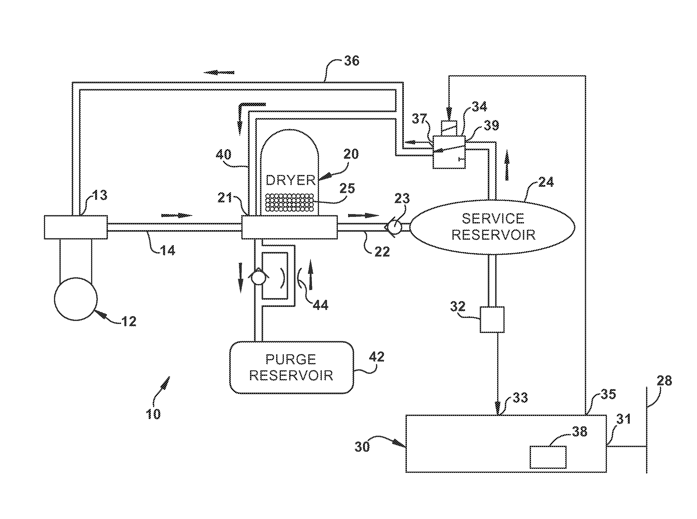
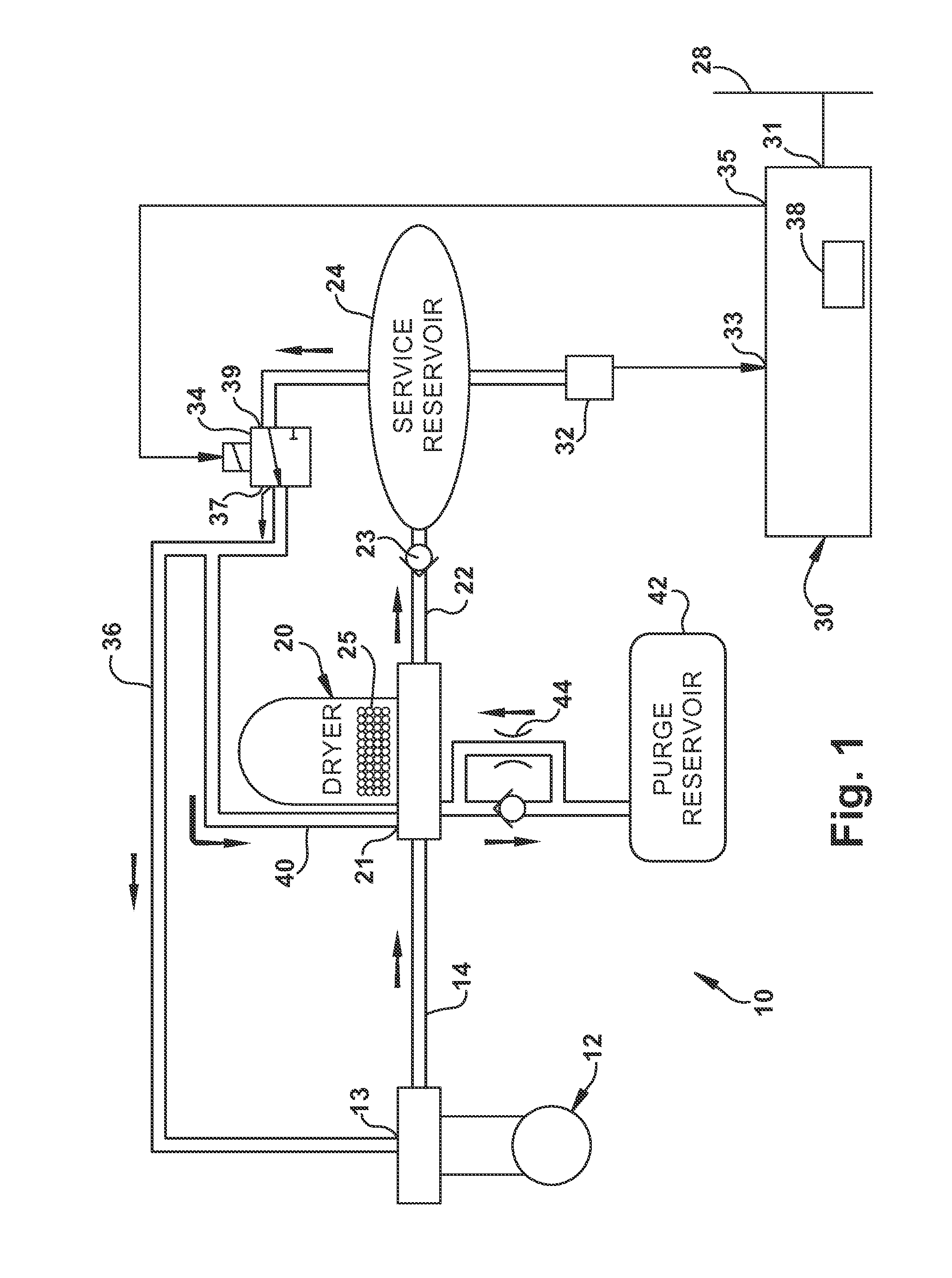
[0014]With reference to FIG. 1, an air charging system 10 for a vehicle according to one embodiment of the present invention is shown. The air charging system 10 includes a compressor 12 for compressing ambient air. The compressor 12 includes a control input 13 for receiving a pneumatic signal. The presence of a pneumatic signal at control input 13 changes the compressor 12 to an unloaded state, where the compressor 12 is not compressing air. The output of the compressor 12 is in fluid communication with an air dryer 20 via line 14.

[0015]The air dryer 20 receives the compressed air from the compressor 12 via line 14 when the compressor 12 is in a charging, or loaded, state. The air dryer 20 is operative to remove moisture from the compressed air, for example, by use of a desiccant 25, and to remove contaminants, such as oil, from the compressed air by use of a filter (not shown). The air dryer 20 includes a control input 21 for receiving a pneumatic signal. The presence of a pneumat...


PUM

PropertyMeasurementUnit
timeaaaaaaaaaa
timeaaaaaaaaaa
pressureaaaaaaaaaa

Abstract

A method and controller for controlling the purge cycling of an air dryer assembly is disclosed. The controller includes a control output for transmitting a control signal for controlling the air dryer. The controller is capable of initiating an enhanced purge cycle for the air dryer based on a regeneration volume value. The regeneration volume value is based on the accumulated volume of air delivered to the air dryer for a first time or since a prior standard purge cycle.

Description

BACKGROUND[0001]The present invention relates to an air dryer assembly for use in a compressed air system for heavy vehicles, locomotives and / or auxiliary devices that use compressed air. Typical heavy vehicle compressed air systems include a compressor for compressing the air, an air dryer assembly for removing moisture and contaminants from the compressed air, a reservoir for storing the compressed air and valves and other pneumatic system components for distributing the compressed air. The present invention finds particular application in conjunction with heavy vehicles that use compressed air to selectively control application of vehicle brakes and will be described with particular reference thereto.[0002]The compressor provides compressed air to a reservoir, the compressed air being used to operate vehicle brakes and other air operated systems associated with the vehicle. Ambient air is typically drawn into a compressor inlet for compression during an air delivery, or charging,...

Claims


Application Information

Patent Timeline
Patent Type & Authority Applications(United States)
IPC IPC(8): B60T17/00B01D53/04
CPCB01D53/0454B60T17/004B01D53/261B01D2258/06B01D2259/40052B60T8/174B60T2210/122
Inventor PFEFFERL, DAVID J.QUINN, LEONARD A.SIPOS, ANDRASWILFING, AARON S.HAMILTON, CORY J.
Owner BENDIX COMML VEHICLE SYST LLC
Why Eureka
Try Eureka