Solar-thermal collector

Inactive Publication Date: 2015-09-10
CHIYODA CORP
View PDF0 Cites 2 Cited by
  • Summary
  • Abstract
  • Description
  • Claims
  • Application Information

AI Technical Summary

Benefits of technology

[0008]The present invention has been made in view of the foregoing circumstances, and a purpose of the invention is to provide

Problems solved by technology

However, constructing the support member having the pipe truss structure requires a lot of labor and cost in the joining of pipes.
Further, the support members having the pipe truss structure are bulky when they are transported to a

Method used


Image

  • Solar-thermal collector
  • Solar-thermal collector
  • Solar-thermal collector

Examples


Example

[0030]The invention will now be described by reference to the preferred embodiments. This does not intend to limit the scope of the present invention, but to exemplify the invention.

[0031]Hereinbelow, a detailed description will be given of embodiments of the present invention with reference to the drawings.

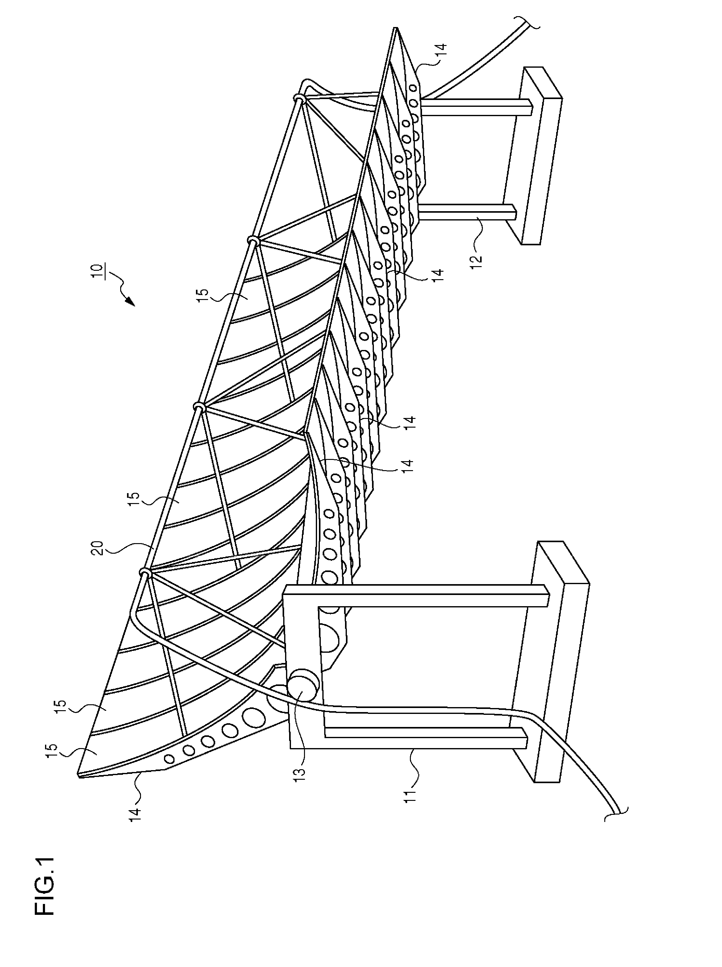
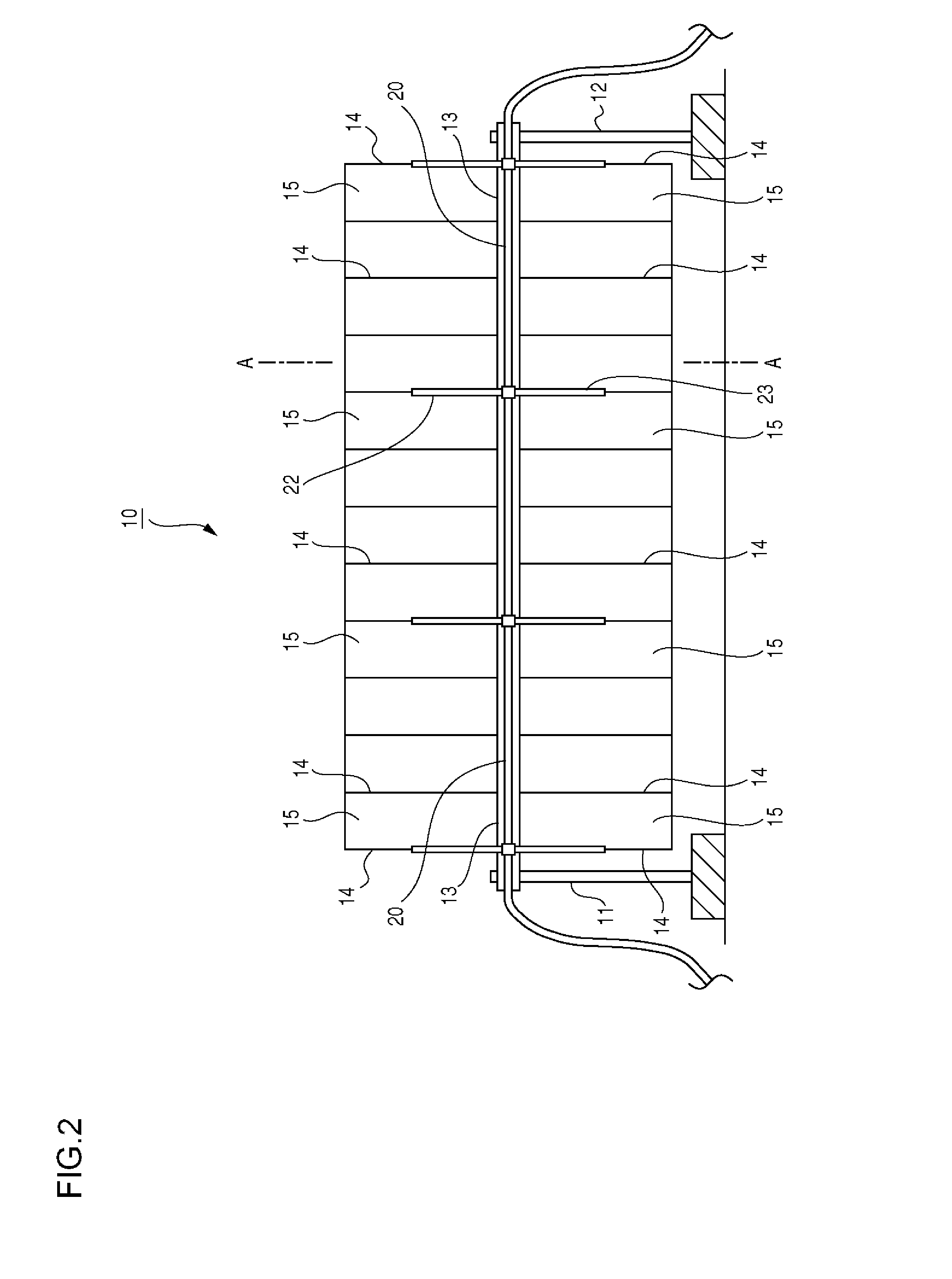
[0032]FIG. 1 is a perspective view of a light condensing apparatus for use in the generation of solar thermal power 10 (hereinafter referred to as “solar-thermal collector 10” or simply “solar collector 10”) according to an embodiment of the present invention. As illustrated in FIG. 1, the solar-thermal collector 10 is comprised mainly of stands 11 and 12 on the ground, a shaft 13, which is rotatably supported by the stands 11 and 12, a plurality of arms 14, which are fixed to the shaft 13 and are arranged at intervals along the length thereof, and a plurality of reflectors 1 supported by the arms 14. The reflection surfaces of reflectors 15 are formed with a parabolic-cylindrica...


PUM

PropertyMeasurementUnit
Lengthaaaaaaaaaa
Shapeaaaaaaaaaa

Abstract

A solar-thermal collector includes a shaft supported by stands, a plurality of plate-like arms, which are secured to the shaft and arranged at intervals in the direction of length of the shaft, a reflector, which is supported by two adjacent arms and which reflects and concentrates the sunlight, and a spacer, which defines the spacing between the two adjacent arms and which is provided between the two adjacent arms.

Description

BACKGROUND OF THE INVENTION[0001]1. Field of the Invention[0002]The present invention relates to a light condensing apparatus for solar thermal power generation (solar-thermal collector or solar collector), a solar thermal power generation system using said solar-thermal collector, and a method for manufacturing a support for a reflector that reflects and concentrates the sunlight.[0003]2. Description of the Related Art[0004]The following solar thermal power generation method is known in the conventional practice. The sunlight is concentrated onto a heat collecting tube by a light condensing apparatus for use in the generation of solar thermal power that uses a curved surface reflecting mirror. And a fluid, such as oil, flowing through the heat collecting tube is heated and a steam turbine is rotated using the fluid heated there so as to generate the electric power. Hereinafter, this light condensing apparatus for use in the generation of solar thermal power will be referred to as a...

Claims


Application Information

Patent Timeline
IPC IPC(8): F03G6/06B23P19/00F24J2/12F24S23/70F24S23/71F24S23/74
CPCF03G6/065F03G2006/061B23P19/00F24J2/12Y02E10/46F03G6/067Y02E10/47F24S2080/09F24S23/74F24S30/425F24S2025/011F24S23/82Y10T29/49355Y02E10/40F03G6/061
Inventor SAITO, HIROKAZUSUZUKI, TOSHIHISA
Owner CHIYODA CORP
Why Eureka
Try Eureka