
Fastening System

a technology of fastening system and bolt, which is applied in the direction of flexible elements, sheet joining, dowels, etc., can solve the problems of lack of flexibility, difficult, if not impossible, to insert the bolt or said similar functional component through the aperture or passageway from said side, and the cross-sectional shape does not facilitate a tight fi

Inactive Publication Date: 2015-09-10
LE GRANGE ANDRIES JOHANNES
View PDF0 Cites 12 Cited by
  • Summary
  • Abstract
  • Description
  • Claims
  • Application Information

AI Technical Summary

Benefits of technology

The patent describes a push-on fastener that is used to securely attach an elongated flexible member to a target. The push-on fastener has an anchor formation or stop formation that can hold the flexible member in place. The flexible member can be made of synthetic plastics or polymeric material, which makes it easier to remove any excess material. The push-on fastener can handle higher tensile forces and has a ratchet formation that prevents the flexible member from being pulled out. The technical effect is an improved secure attachment of flexible members to targets.

Problems solved by technology

Often, it is necessary to insert a bolt or a similar functional component with an elongate rigid part such as a shank through an aperture or passageway in an object, where access to the aperture from one particular side is restricted thus making it very difficult, if not impossible, to insert the bolt or said similar functional component through the aperture or passageway from said side.
A further drawback of known fastener systems incorporating ratchets is that they either: (i) lack flexibility sufficient to permit the shank to pass through a passageway in an object that is not right circular cylindrical; or (ii) where they are sufficiently flexible, their cross-sectional shape does not facilitate a tight fit between the cross-sectional circular passageway in the object and the shank.

Method used


Image

  • Fastening System
  • Fastening System
  • Fastening System

Examples


Embodiment Construction

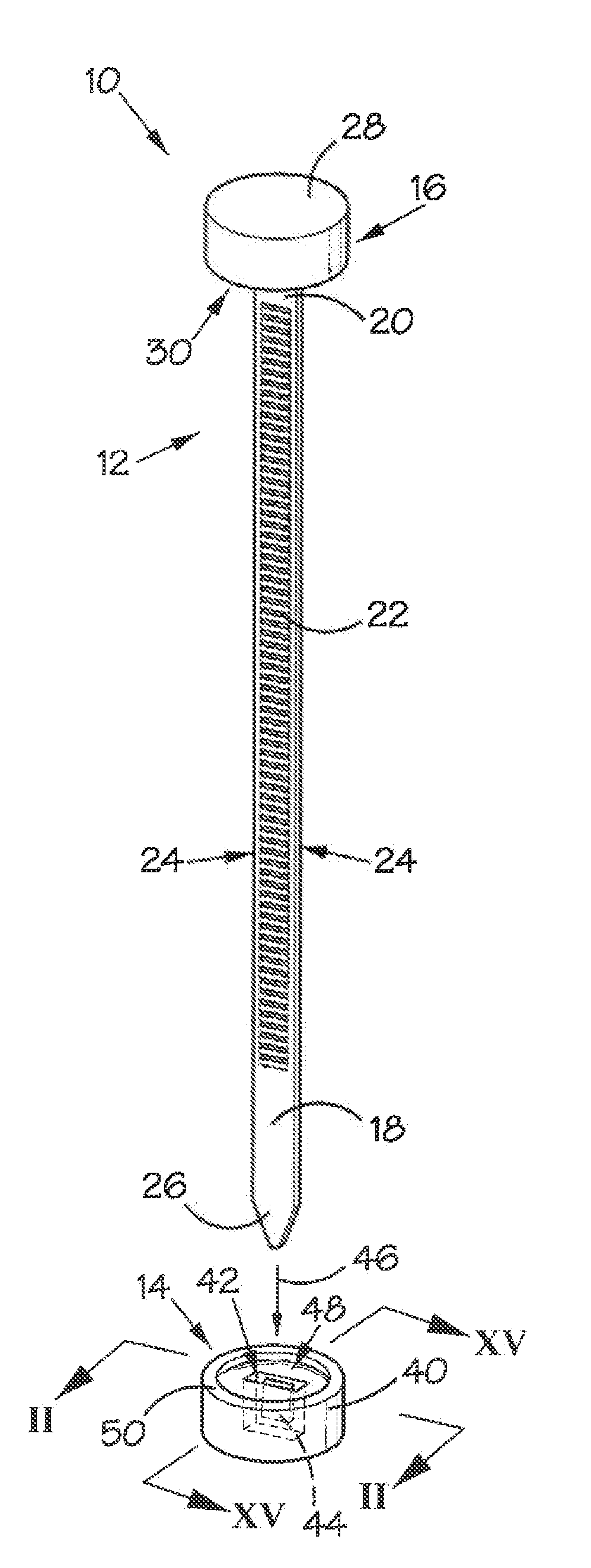
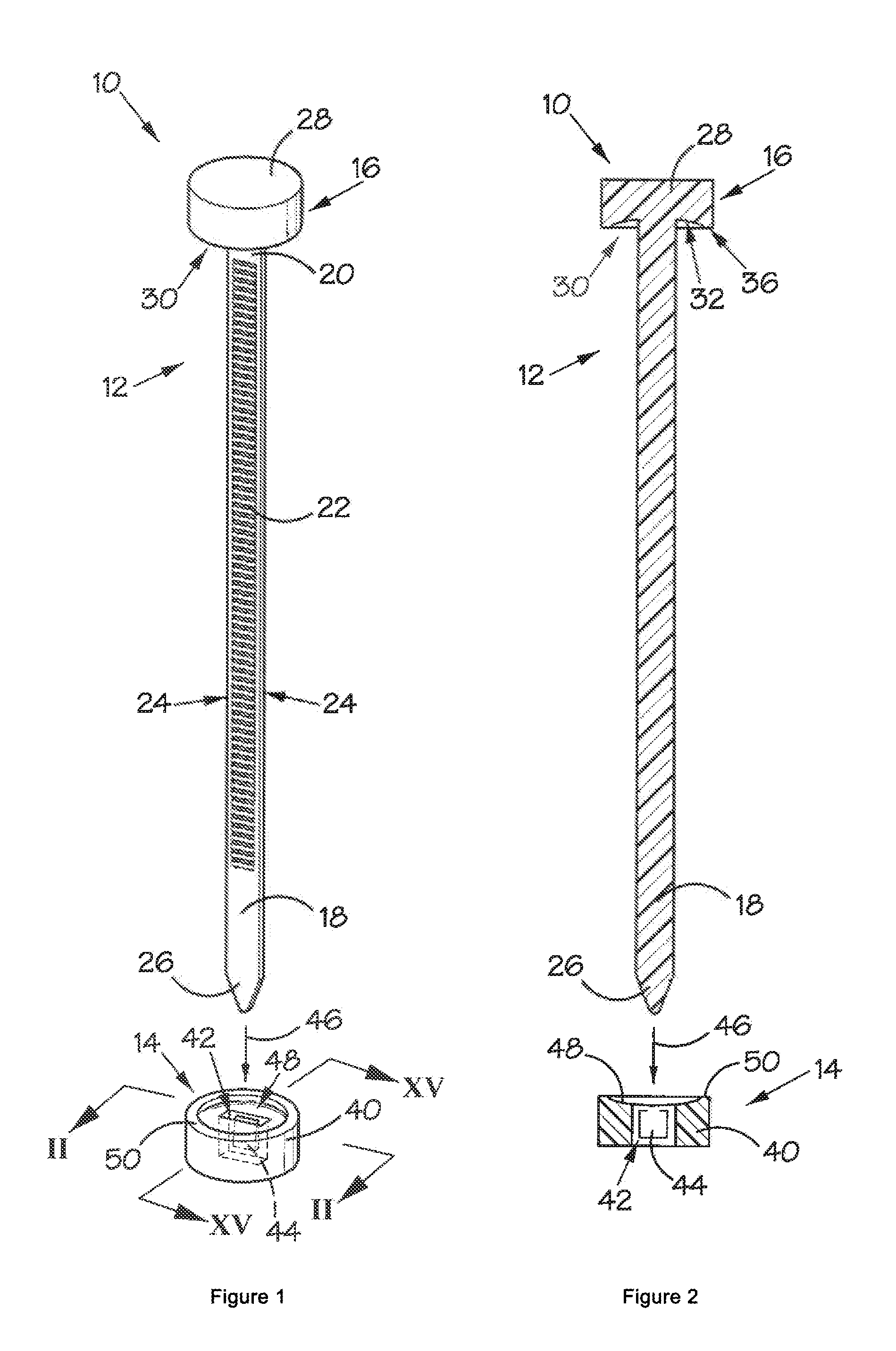
[0090]Referring to FIGS. 1 and 13 of the drawings, reference numeral 10 generally indicates a two-component fastening system in accordance with the invention. The system 10 includes an anchor component 12 and a push-on fastening component 14.

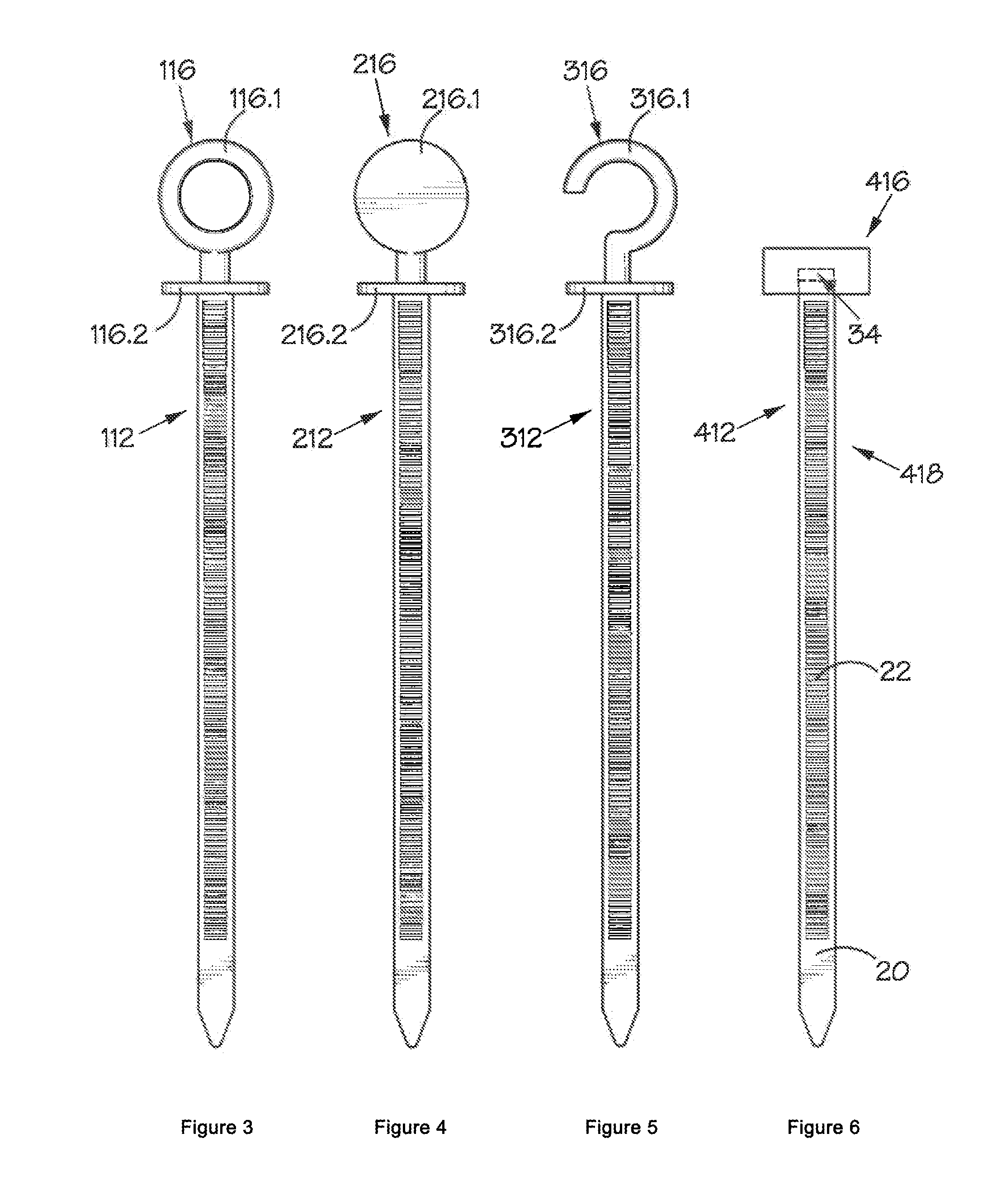
[0091]In the embodiment of the two-component fastening system shown in FIG. 1 of the drawings, the anchor component 12 includes a solid head 16 of nylon 6.6 integrally moulded with an elongate flexible member in the form of a solid strap 18, also of nylon 6.6.

[0092]The strap 18 extends centrally from a bottom of the head 16 and resembles the strap of a conventional cable tie. Thus, the strap 18 has opposed major faces 20 (which are planar when the strap 18 is pulled straight or flattened in another way) with a series of ratchet formations 22 arranged longitudinally along the length of the strap 18, on the major faces 20. Minor faces 24 form sides of the strap 18, extend between the major faces 20 and are smooth. In the embodiment shown in FIG. 1...


PUM


Abstract

Disclosed is a fastening system (10) including an anchor component (12) having a head (16) and an elongate flexible member (18) extending from the head (16). The elongate flexible member (18) has one of the following cross-sections: (i) a circle with at least one segment removed to provide at least one linear cord; (ii) a shape wherein at least three equally spaced arms of the same length radiate radially from the longitudinal axis; or (iii) a polygon made up of linear sections of substantially the same length. At least one series of ratchet formations (22) is provided on a planar surface of the elongate flexible member (18). The fastening system (10) furthermore comprises a push-on fastening component (14) which is separate from, or prior to use severable from, the anchor component (12). The push-on fastening component (14) defines a passageway (42) to receive the elongate flexible member (18) and having at least one ratchet formation engaging member (44) to engage the ratchet formations (22) to allow passage of the elongate flexible member (18) through the passageway (42) in one direction but not in the other direction. The push-on fastening component (14), unlike the anchor component (12), does not include an elongate flexible member with a series of longitudinally arranged ratchet formations.

Description

BACKGROUND[0001]THIS INVENTION relates to fasteners. In particular, the invention relates to a two-component fastening system, to an anchor component intended for use as part of a two-component fastening system, to a push-on fastening component intended for use as part of a two-component fastening system.[0002]Two-component fastening systems, such as threaded nut-and-bolt fastening systems, and ratchet nut and bolt fastening systems, are well-known in the art. Often, it is necessary to insert a bolt or a similar functional component with an elongate rigid part such as a shank through an aperture or passageway in an object, where access to the aperture from one particular side is restricted thus making it very difficult, if not impossible, to insert the bolt or said similar functional component through the aperture or passageway from said side. A two-component fastening system which addresses at least to some extent this problem would be desirable.[0003]A further drawback of known fa...

Claims


Application Information

Patent Timeline
Patent Type & Authority Applications(United States)
IPC IPC(8): F16B19/00F16M13/02B65D63/10
CPCF16B19/00F16M13/02B65D63/1063F16B2/08F16B5/0642F16B13/124F16B21/073F16B45/008Y10T24/45005Y10T24/45115Y10T24/4523Y10T24/45246
Inventor LE GRANGE, ANDRIES JOHANNES
Owner LE GRANGE ANDRIES JOHANNES
Learn More