Addressability in particle detection

Active Publication Date: 2015-09-10
GARRETT THERMAL SYST LTD
View PDF5 Cites 28 Cited by
  • Summary
  • Abstract
  • Description
  • Claims
  • Application Information

AI Technical Summary

Benefits of technology

[0160]The method can include providing the correlation data to the video capture system to enable selective capture, storage or display of images relating to corresponding to an address in the p

Problems solved by technology

One recognised difficulty with air sampling systems as described above is that they do not identify through which air inlet smoke enters the system.
However, this inferential process is often unreliable.
However, this process may be inaccurate.
More specifically, an increase in smoke level, such as that caused by a fire of growing size, may result in an inaccurate estimate of the geographical location from which air has been drawn.
However, this is difficult to achieve as various features influence the operation of the fall, e.g. degradation of the aspiration system over time and variations in operational and environmental conditions e.

Method used


Image

  • Addressability in particle detection
  • Addressability in particle detection
  • Addressability in particle detection

Examples


Embodiment Construction

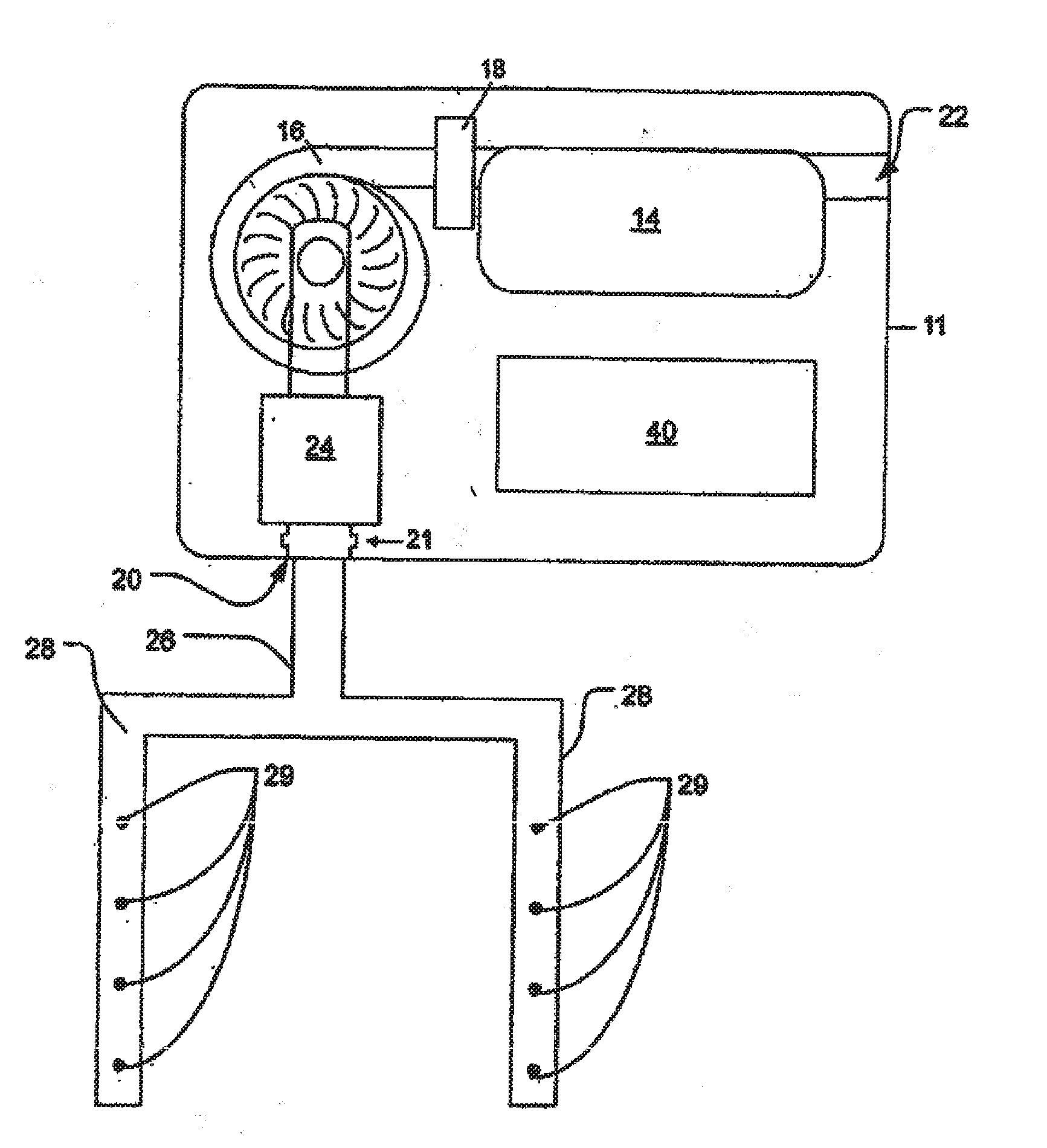
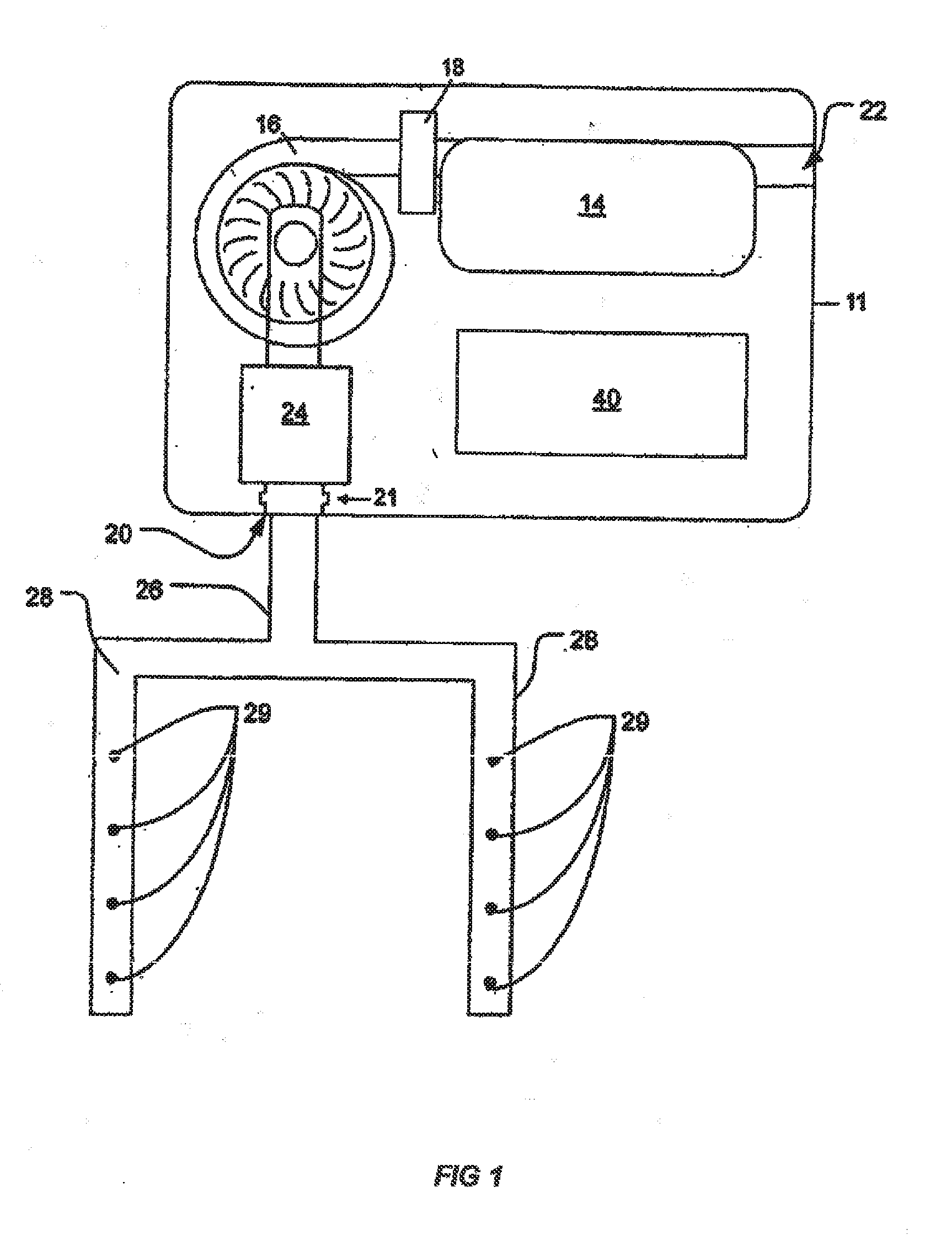
[0203]FIG. 1 shows a particle detection system including a particle detector 11 in fluid communication with a sampling network 28. The sampling network includes a plurality of inlets 29 through which air is drawn. An aspirator 16 draws air into the sampling network 28 through inlet 21 and along into a particle detection chamber 14. Air sample exits the detection system through outlet 22.

[0204]The detector includes a flow sensor 24. In a preferred embodiment of the present invention, an ultrasonic flow sensor as described in WO 2004 / 102499 is employed. This sensor enables volumetric flow measurements to be made. The flow sensor 24 provides an indication of the volume of air flowing into the particle detector 10 from the sampling network 28 per unit time. The output of the flow sensor 24 may be used to infer, for example, when flow faults e.g. a blockage of the sampling network 28 or reduced aspirator performance, has occurred.

[0205]The system 10 also includes a controller 40 for dete...


PUM


Abstract

A method of determining at least one point of entry of smoke into a smoke detection system, the system having a sampling pipe network including at least one sampling pipe and a plurality of sampling inlets through which an air sample can enter the at least one sampling pipe of the smoke detection system for analysis by a particle detector, said method including: determining a volume of sample air that has passed through at least part of the smoke detection system since a predetermined event or a value corresponding to said volume; and determining through which sampling inlet of the plurality of sampling inlets the smoke entered the smoke detection system based, at least in part, on the determined volume or value. Systems for implementing such a method and related methods are also described.

Description

RELATED APPLICATIONS[0001]This application claims the benefit of Australian provisional patent applications: 2012904516, filed 16 Oct. 2012; 2012904854, filed 2 Nov. 2012; 2013902076, filed 7 Jun. 2013; and 2013902570 filed 11 Jul. 2013; and Australian complete patent application 2013200353, filed 21 Jan. 2013, each of which are incorporated herein by reference for all purposes.BACKGROUND OF THE INVENTION[0002]1. Field of the Invention[0003]The present invention relates to particle detection. For illustrative purposes only, the preferred embodiment of the present invention will be described in relation to a smoke detection system, but the invention should not be considered to be limited to that exemplary use.[0004]2. Discussion of the Related Art[0005]Air sampling or aspirated smoke detection systems operate by drawing air samples through a sampling network, to a central high sensitivity particle detector. The sampling network typically includes one or more sample pipes with a numbe...

Claims


Application Information

Patent Timeline
IPC IPC(8): G01F1/66G01N15/14
CPCG01N15/1434G01F1/66G01N2015/0046G01N1/24G01N15/06G08B17/10G01N2001/245G08B17/113G01N1/26
Inventor AJAY, KEMALKNOX, RONALEXANDER, BRIANBOETTGER, KARLSINGH, RAJIV KUMARNORTH, THORPATTINSON, STEPHEN JAMESMASSINGBERD-MUNDY, PETER
Owner GARRETT THERMAL SYST LTD
Why Eureka
Try Eureka