Fiber optic vault security system

a security system and fiber optic technology, applied in the field of enclosed vault security systems, can solve the problems of not being able to remove the security panel from the frame without, not being able to detect a significant reduction in light, and not being able to open or remove the cesium (or other nuclear material)

Active Publication Date: 2015-09-10
BE AEROSPACE INCORPORATED
View PDF13 Cites 9 Cited by
  • Summary
  • Abstract
  • Description
  • Claims
  • Application Information

AI Technical Summary

Benefits of technology

[0010]The enclosed vault security system includes a metal cage with security panels affixed thereto, forming a vault in which an item of value, such as a blood irradiator machine, is enclosed. The security panels are formed of a first substrate on which a fiber optic security cable is laid on the substrate, preferably in a sinusoidal pattern with nested fiber loops for added security. Adhesive tape may be used to hold the fiber cable in place, while a second sheet of laminate is adhered to the other side so that the optic cable is sandwiched between the substrates to complete a single security panel. The cage includes the security panels on the sides, front, and possibly the top to form the vault enclosure. A front door includes an opening giving access to the irradiator control panel and other operative features when closed. However, the opening does not permit access or removal of the Cesium (or other nuclear material) contained within the irradiator machine. Fiber optical sensor cables are connected to each security panel at one end, and the cables are then routed through the tubular frame members to a control box. In one embodiment, the fiber optic cables

Problems solved by technology

However, the opening does not permit access or removal of the Cesium (or other nuclear material) contained within the irradiator machine.
The security panel cannot be removed from the frame wi

Method used


Image

  • Fiber optic vault security system
  • Fiber optic vault security system
  • Fiber optic vault security system

Examples


Embodiment Construction

Overview

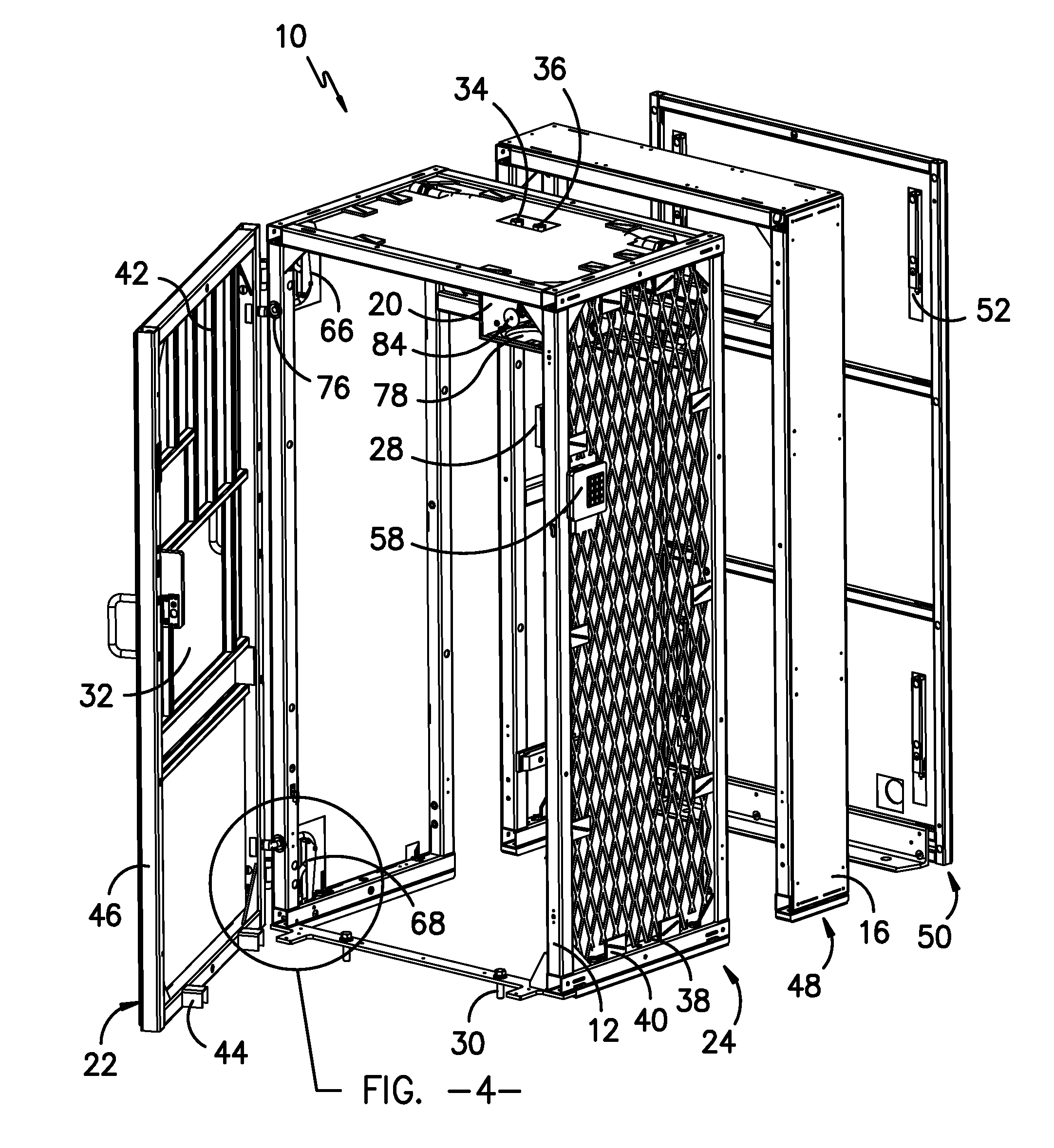
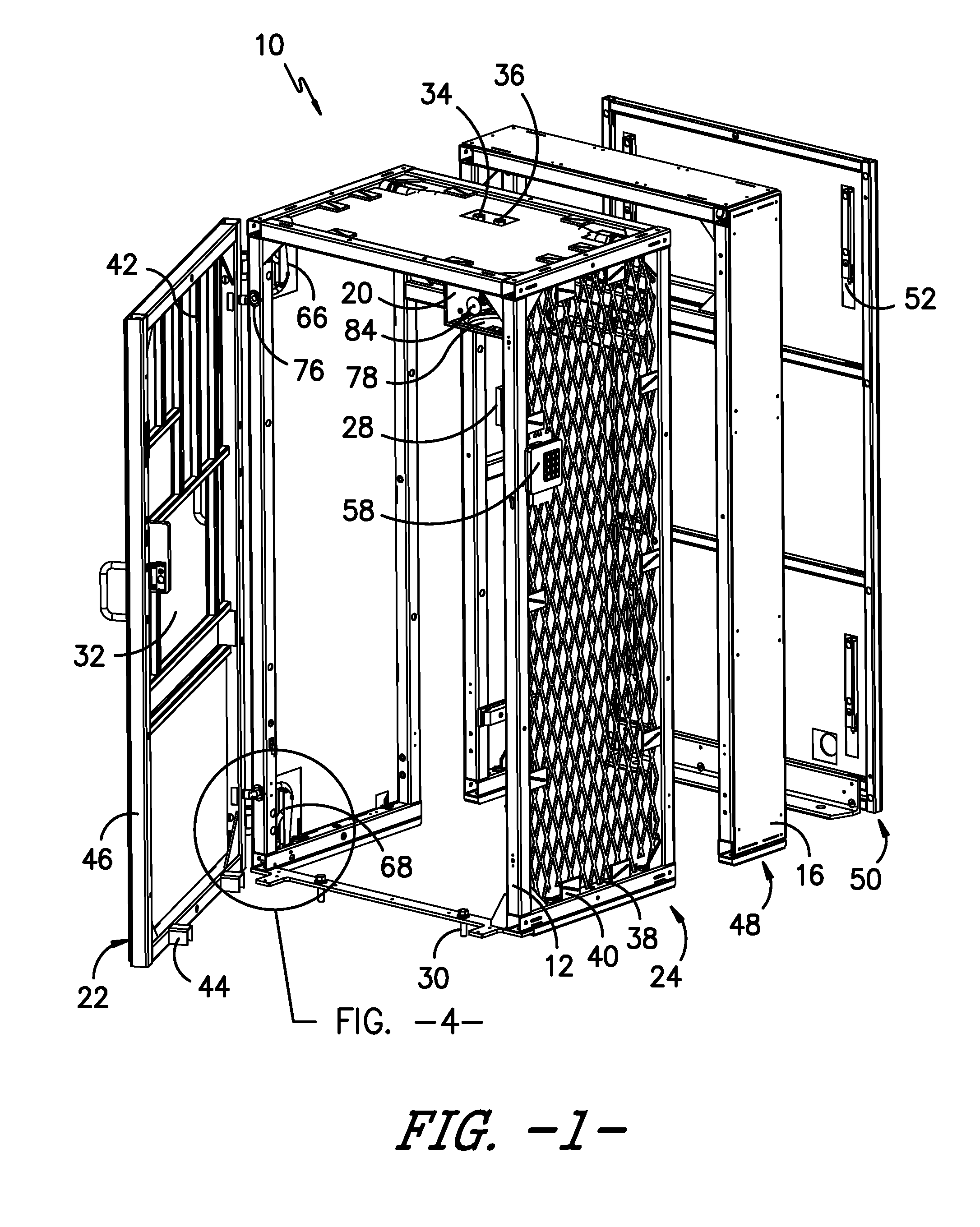
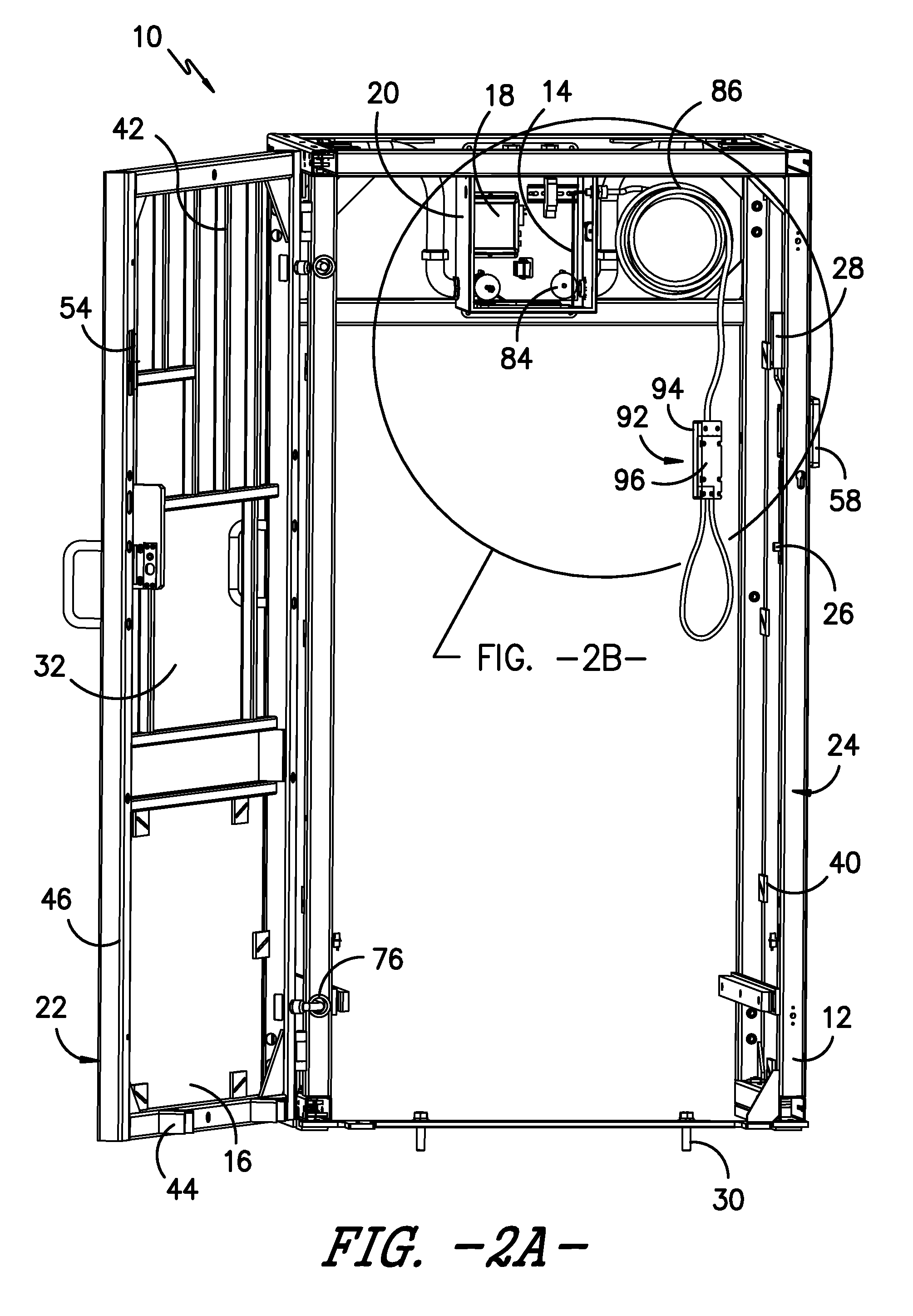
[0035]Several embodiments of an enclosed security system are shown in FIGS. 1, 2A, 5A, 7A, 11A. In a first embodiment, the enclosed security system 10 (also referred to herein as a “booth,”“vault,” or “cage”) preferably includes a 4-sided cage structure 24 (having no bottom or rear panel in some embodiments) that can be shipped fully assembled and ready for installation on site. The cage frame 12 is preferably fabricated from ERW structural steel tubing and each exterior surface of the cage is covered with a laminated sheet containing fine-diameter fiber optic cable 14. The fiber panels 16 are monitored by a light source / receiver processor (“light processor”) 18 installed within an enclosure 20 that is mounted inside the security cage. It is contemplated that a bottom and / or rear panel may be incorporated into the present device, if desired, and other suitable materials may be used for the frame or cage structure, such as aluminum, fiberglass, or the like.

[0036]The door 22 o...


PUM


Abstract

An enclosed security system includes a metal cage with security panel affixed thereto, forming a vault in which an item of value is enclosed. The security panels include a series of fiber optic security cables, preferably arranged in a sinusoidal pattern with nested fiber loops for added security. The cage preferably includes the security panels on the sides, front, top and door to form the vault enclosure. Fiber optical sensor cables are routed through the tubular frame members to a control box. An optical security tether may optionally be connected between the control box and a protected asset. The tether preferably comprises a jacketed fiber optic cable with internal strength member, surrounded by a metallic armored flex sheath. Any breakage or disconnection of the fiber optic cables within the panels or tether from the control box is detected by the monitor, causing an alert signal.

Description

BACKGROUND OF THE INVENTION[0001]The present invention generally relates to enclosed vault security systems, similar to safes, wherein items of value may be stored and protected against access by unauthorized personnel. More specifically, the present invention includes an enclosure or vault having a series of panels and at least one door, wherein each panel and the door include an embedded fiber optic line arranged either in a random configuration or in a pattern, such that any cut or tight bend in the fiber optic line results in an alarm signal, or other desired alarm output. The present invention has a particularly useful application with respect to blood irradiators, which are found in many hospitals and contain nuclear material that must be protected against theft.[0002]Other types of secured enclosures have been developed heretofore. For example, U.S. Pat. No. 8,344,885 discloses a large shipping container with side panels of a composite material having a security element embed...

Claims


Application Information

Patent Timeline
IPC IPC(8): G08B13/186G01V8/16
CPCG01V8/16G08B13/186B65B25/02E05G1/024G01J1/0425G08B13/124G08B13/126G08B13/1463
Inventor KNIGHT, PHILIP A.HANLIN, R JOSH
Owner BE AEROSPACE INCORPORATED
Why Eureka
Try Eureka