Cooling device and cooling arrangement including cooling device

Active Publication Date: 2015-09-10
HKR AUTOMOTIVE GMBH
View PDF10 Cites 6 Cited by
  • Summary
  • Abstract
  • Description
  • Claims
  • Application Information

AI Technical Summary

Benefits of technology

[0017]Therefore it is the object underlying the present invention to configure a cooling arrangement comprising a cooling device of the

Problems solved by technology

Especially semiconductor components and specifically power transistors show particular electric dissipation losses which are dependent on the type and the operation and are not to be neglected so that partly considerable heating occurs.
The afore-con

Method used


Image

  • Cooling device and cooling arrangement including cooling device
  • Cooling device and cooling arrangement including cooling device
  • Cooling device and cooling arrangement including cooling device

Examples


Embodiment Construction

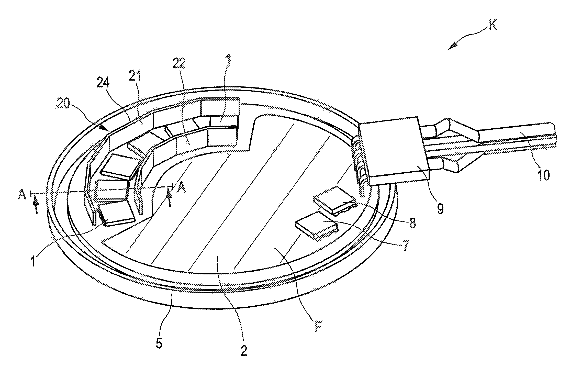
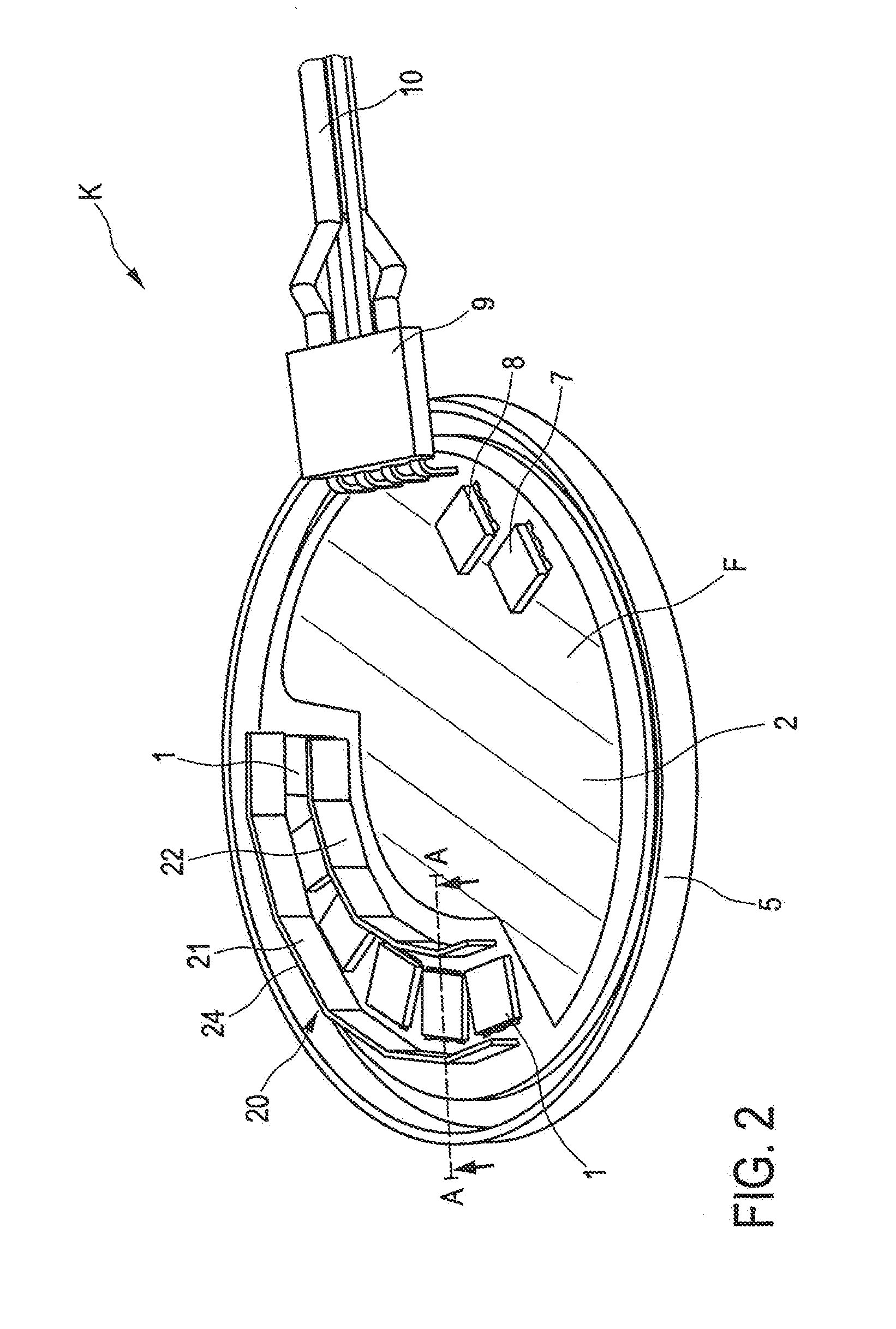
[0040]Hereinafter the present invention will be described by way of an embodiment with reference to the FIGS. 1 and 2 as regards the basic structure of the present invention.

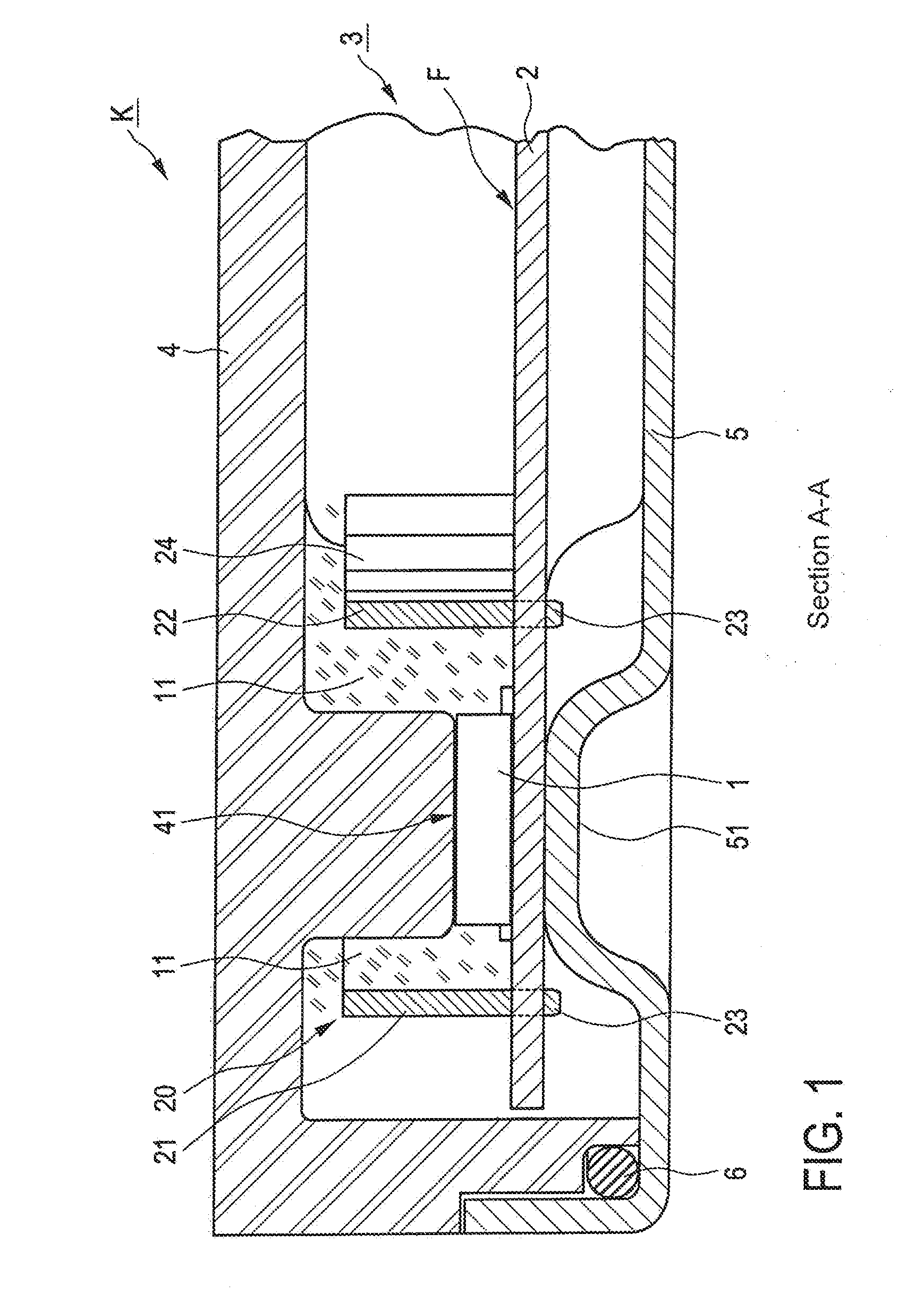
[0041]FIG. 1 shows a partial sectional view of the arrangement of a heat-emitting component 1 in connection with the cooling arrangement K according to the invention.

[0042]The heat-emitting component 1, hereinafter simply referred to as component 1, can be a power semiconductor component such as a transistor or else, having a different outer shape, an electrolyte capacitor. The invention is neither fixed to a particular component nor to a particular outer shape of such component 1. Rather, it can be used for any type of components which emit heat during operation or at least in specific operating conditions due to power dissipation.

[0043]The component 1 is arranged on a printed circuit board 2 which can include, apart from the component 1 shown for the purpose of illustration of the present invention, further co...


PUM


Abstract

The invention relates to a cooling device for heat-emitting components, wherein at least one component is arranged on a printed circuit board and wherein the cooling device includes a first cooling member and a second cooling member. The two cooling members are arranged on the printed circuit board adjacent to and at a predetermined distance from the at least one component on opposite sides of the component. The invention further relates to a cooling arrangement for cooling at least one heat-emitting component arranged on a printed circuit board, wherein use is made of the cooling device.

Description

CROSS REFERENCE TO RELATED APPLICATION[0001]This application claims priority under 35 USC §119 to Germany Patent Application No. 20 2014 002 060.4 filed on Mar. 6, 2014, which application is hereby incorporated by reference in its entirety.TECHNICAL FIELD[0002]The present invention relates to a cooling device for electric and electronic components and especially to a cooling device as part of a cooling arrangement, the cooling device being provided in addition.BACKGROUND OF THE INVENTION[0003]In electric and electronic circuits a plurality of different components is used for providing a particular function. In dependence on the type of the respective component and the load of the components in connection with the electric values of current and voltage, at least some of the components constitute heat sources of different thermal capacity and thus different heat transfer. Especially semiconductor components and specifically power transistors show particular electric dissipation losses...

Claims


Application Information

Patent Timeline
IPC IPC(8): H05K7/20
CPCH05K7/20509H05K7/20436H05K7/20445
Inventor BASS, WOLFGANG
Owner HKR AUTOMOTIVE GMBH
Why Eureka
Try Eureka