Motor vehicle with a cooling system

a technology for motor vehicles and cooling systems, applied in the direction of electrochemical generators battery/fuel cell control arrangements, etc., can solve the problems of limited functionalities or relatively complicated designs of cooling systems disclosed therein, and achieve the effect of sufficient cooling effect and quick and energetically advantageous heating of the interior

Active Publication Date: 2019-03-07
VOLKSWAGEN AG
View PDF3 Cites 11 Cited by
  • Summary
  • Abstract
  • Description
  • Claims
  • Application Information

AI Technical Summary

Benefits of technology

[0011]In one embodiment of the air conditioner that includes at least a cycle apparatus, it may be provided to operate the air conditioner in the first functional position of the distribution system as a heat pump, so that the waste heat of the first coolant circuit that is absorbed in the coolant-refrigerant heat exchanger, together with in particular energy (overpressure) that is introduced into the refrigerant from the compressor, as useful heat in the condenser is transferred to the air that is provided for controlling the temperature of the interior of the motor vehicle. Since the thermal energy (waste heat) that is absorbed by the coolant when flowing through the first coolant circuit is preferably to be utilized solely for heating the interior of the motor vehicle, it is provided that the first coolant circuit integrates the bypass to the ambient heat exchanger, so that the coolant is at least partially, and preferably completely, led across this bypass. Accordingly, the ambient heat exchanger itself may preferably not be integrated into the first coolant circuit, and therefore coolant also does not flow through it.
[0012]In addition, in the first functional position of the distribution system it is provided that by means of the second coolant pump, coolant is conveyable in a second coolant circuit, separate from the first coolant circuit, that includes (preferably in addition to the second coolant pump) solely the traction battery and the coolant heater. In one refinement of the method according to the invention, this makes it possible to control the temperature of (in particular solely) the traction battery by means of the coolant heater, as the result of which the coolant heater may be heated, preferably rapidly and with the least possible use of thermal energy to be generated by the coolant heater, until an intended operating temperature is reached.
[0013]It may be meaningful to operate the motor vehicle or the cooling system, based on the first functional position of the distribution system, in particular directly or shortly after a cold start of the motor vehicle, i.e., a start-up after the components of the motor vehicle have essentially completely cooled to ambient temperature, at the same time at relatively low ambient temperatures, in order to achieve preferably rapid and energetically advantageous heating of the interior of the motor vehicle and of the traction battery.
[0014]According to the invention, “separation” of various cooling circuits of the cooling system of a motor vehicle according to the invention is understood to mean that no relevant exchange of coolant takes place between these cooling circuits during operation of the cooling system, i.e., when coolant is conveyed by means of the coolant pumps.
[0015]According to the invention, in addition a second functional position of the distribution system is provided in which on the one hand coolant is conveyable, by means of the first coolant pump, in a third coolant circuit that includes the traction motor and the ambient heat exchanger, and on the other hand coolant is conveyable, by means of the second coolant pump, in a fourth coolant circuit, separate from the third coolant circuit, that includes the traction battery and the coolant-refrigerant heat exchanger. Thus, in the method according to the invention, in the second functional position of the distribution system it may be provided to utilize thermal energy, transferred in the coolant-refrigerant heat exchanger from the coolant flowing through the fourth coolant circuit to the refrigerant of the air conditioner, for cooling the traction battery; i.e., active cooling of the traction battery is then provided by means of the air conditioner via the coolant circulating in the fourth coolant circuit. Accordingly, in one embodiment of the air conditioner that at least includes a cycle apparatus, it may be provided to operate the air conditioner in the second functional position of the distribution system as a refrigeration unit. At the same time, it may be provided that waste heat that is transferred from the components, in particular the traction motor, that are integrated into the third coolant circuit, to the coolant circulating therein is discharged from the cooling system or the motor vehicle via the ambient heat exchanger, which is then at least partially, preferably completely, integrated into the coolant circulation.
[0016]An operation of the motor vehicle or the cooling system based on the second functional position of the distribution system may be provided in particular after all components that are integrated into the cooling system, and for which a cooling effect is to be achieved, at least temporarily, by means of the cooling system have in each case reached a defined operating temperature range. As a supplement, it may also be provided that the second functional position of the distribution system is set only when the temperature of the coolant upstream from the traction battery is above a defined limit temperature or a defined limit temperature range, for example between 25° C. and 35° C., wherein the specific limit temperature within this range may vary in particular as a function of the load under which the traction motor is operated. A sufficient cooling effect for the traction battery may then be ensured by the active cooling of the traction battery by means of the air conditioner.

Problems solved by technology

However, the cooling systems disclosed therein are functionally limited or have relatively complicated designs.

Method used


Image

  • Motor vehicle with a cooling system
  • Motor vehicle with a cooling system
  • Motor vehicle with a cooling system

Examples


Embodiment Construction

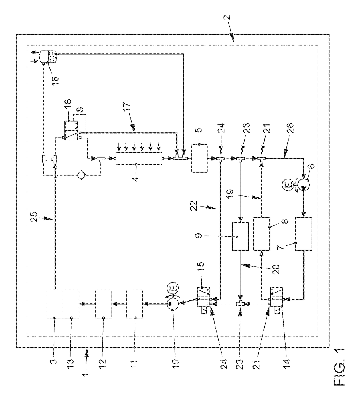
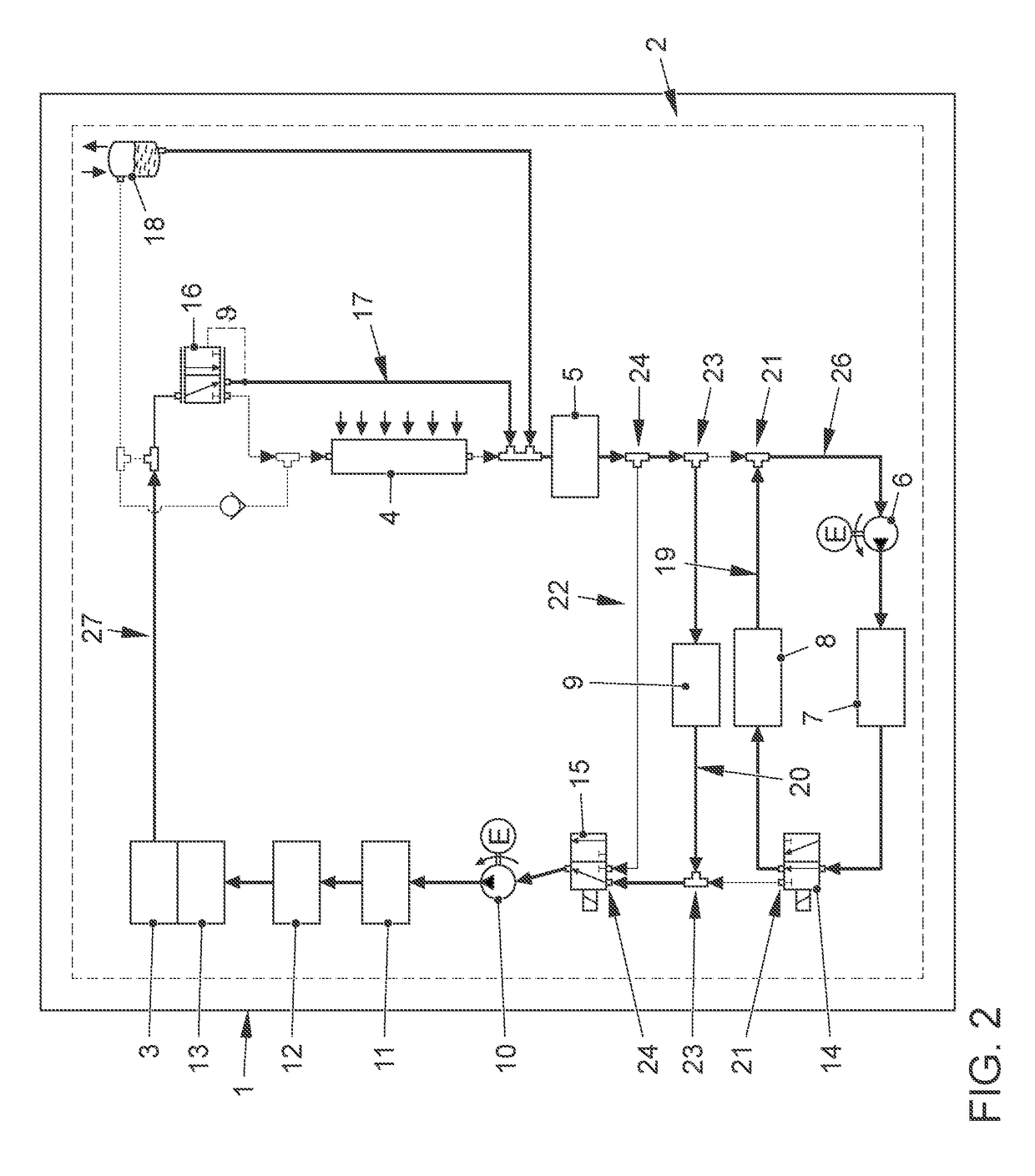
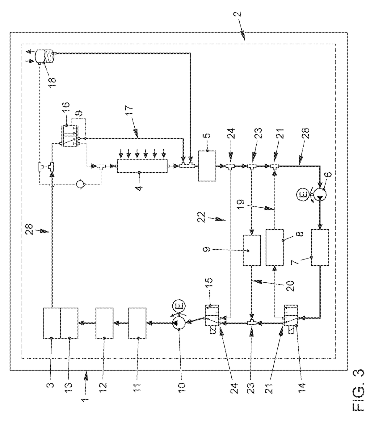
[0038]FIGS. 1 through 5 show in greatly simplified illustrations a motor vehicle 1 according to the invention with a cooling system 2. The cooling system 2 includes, as components to be integrated, an electric traction motor 3, an ambient heat exchanger 4, a DC-DC converter 5, a second electric coolant pump 6, a traction battery 7, an electric coolant heater 8, a coolant-refrigerant heat exchanger 9 of an air conditioner (not illustrated), a first electric coolant pump 10, a first charging device 11, based on inductive energy transfer, for charging the traction battery 7, a second charging device 12 for charging the traction battery 7, in which an electrically conductive connection to an electrical energy source is to be established by means of a plug-in connection, and power electronics 13, associated with the traction motor 3, which may in particular include a pulse-controlled inverter. These components of the cooling system are [connected] by a plurality of coolant lines and by m...


PUM


Abstract

A motor vehicle with a cooling system, comprising an electric traction motor, an ambient heat exchanger, a bypass to the ambient heat exchanger, a traction battery, a coolant heater, a coolant-refrigerant heat exchanger of an air conditioner, a first coolant pump, and a second coolant pump that are directly or indirectly connected or connectable to one another via coolant lines and a distribution system, characterized in that, in a first functional position of the distribution system, coolant is conveyable, by means of the first coolant pump, in a first coolant circuit that includes the traction motor, the bypass to the ambient heat exchanger, and the coolant-refrigerant heat exchanger, and coolant is conveyable, by means of the second coolant pump, in a second coolant circuit, separate from the first coolant circuit, that includes the traction battery and the coolant heater, and in a second functional position of the distribution system, coolant is conveyable, by means of the first coolant pump, in a third coolant circuit that includes the traction motor and the ambient heat exchanger, and coolant is conveyable, by means of the second coolant pump, in a fourth coolant circuit, separate from the third coolant circuit, that includes the traction battery and the coolant-refrigerant heat exchanger.

Description

CROSS-REFERENCE TO RELATED APPLICATIONS[0001]This application claims priority from German Patent Application No. 10 2017 120 615.9, filed Sep. 7, 2017, the entire contents of which are incorporated herein in its entirety.FIELD OF THE INVENTION[0002]The invention relates to an electric motor vehicle, i.e., a motor vehicle that has an electric traction motor, with a cooling system.BACKGROUND OF THE INVENTION[0003]The cooling system of an electric motor vehicle, regardless of whether it is designed in the form of a hybrid vehicle or as a purely electric vehicle, differs significantly from a cooling system of a motor vehicle that is driven solely by means of an internal combustion engine. This is true not only because components of the electric traction system, in particular the electric traction motor and a traction battery provided for supplying this traction motor with electrical energy, must be cooled, perhaps additionally, in such an electric motor vehicle, but also in particular b...

Claims


Application Information

Patent Timeline
Patent Type & Authority Applications(United States)
IPC IPC(8): B60K11/02B60L11/18
CPCB60K11/02B60L11/1874H01M10/613H01M10/625H01M10/663B60H1/00271B60H1/00278B60H2001/00307B60H1/00385B60H1/00392B60H1/3204H01M2220/20H01M10/6568B60H1/32281Y02E60/10B60L58/26
Inventor LUCKE, STEFANSCHULZE, TOBIASSTELZNER, ROBERTREUTERS, ULF
Owner VOLKSWAGEN AG
Why Eureka
Try Eureka