Control apparatus for an internal combustion engine

a control apparatus and internal combustion engine technology, applied in the direction of electrical control, machine/engine, electric control of exhaust gas treatment, etc., can solve the problems of excessive temperature discharge of air sucked into internal combustion engine, and sintering of precious metal catalyst supported by the part, etc., to suppress the occurrence of thermal stress, sufficient cooling effect, and suppress the effect of unnecessary cooling of exhaust gas purification catalys

Active Publication Date: 2017-05-25
TOYOTA JIDOSHA KK
View PDF16 Cites 11 Cited by
  • Summary
  • Abstract
  • Description
  • Claims
  • Application Information

AI Technical Summary

Benefits of technology

[0014]According to such an arrangement, when the temperature of the exhaust gas purification catalyst is less than the predetermined temperature at the time of the execution of the fuel cut off processing, the valve body of the waste gate valve will be fully closed. In that case, the entire exhaust gas will pass through the turbine, and will flow into the exhaust gas purification catalyst. Here, when the valve body of the waste gate valve is made to open at the time of the temperature of the exhaust gas purification catalyst being lower than the predetermined temperature and at the same time of the fuel cut off processing being carried out, a part of exhaust gas (air) of low temperature discharged from the internal combustion engine will flow into the exhaust gas purification catalyst by way of the bypass passage. Because the exhaust gas passing through the bypass passage is less susceptible to the heat of the turbine, it will flow into the exhaust gas purification catalyst in a low temperature state. As a result, there is a possibility that the exhaust gas purification catalyst is cooled unnecessarily. On the other hand, when the valve body of the waste gate valve is made to fully close at the time of the temperature of the exhaust gas purification catalyst being lower than the predetermined temperature and at the time of the fuel cut off processing being carried out, all the exhaust gas of low temperature discharged from the internal combustion engine will flow into the exhaust gas purification catalyst by way of the turbine. As a result, the exhaust gas warmed by receiving the heat of the turbine will flow into the exhaust gas purification catalyst, so that unnecessary cooling of the exhaust gas purification catalyst can be suppressed as much as possible.
[0015]On the other hand, when the temperature of the exhaust gas purification catalyst is equal to or more than the predetermined temperature and when the fuel cut off processing is carried out, it is desirable to cool the exhaust gas purification catalyst by the exhaust gas of low temperature which has not passed through the turbine. However, when the temperature of the exhaust gas purification catalyst is equal to or more than the predetermined temperature and at the same time the fuel cut off processing is carried out, the occurrence of thermal stress and the occurrence of sintering may be caused, as mentioned above, when the amount of exhaust gas impinging directly against the part of the upstream side end face of the exhaust gas purification catalyst (hereinafter, referred to as an “upstream side catalyst end face”) among the exhaust gas of low temperature having not passed through the turbine becomes large. Accordingly, when the temperature of the exhaust gas purification catalyst is equal to or more than the predetermined temperature at the time of the execution of the fuel cut off processing, the control apparatus for an internal combustion engine of the present disclosure controls the degree of opening of the valve body of the waste gate valve to the deterioration suppression opening degree which is larger than when the valve body is fully closed (i.e., fully closed opening degree), but smaller than the predetermined degree of opening. Here, the exhaust gas flowing out from the outlet of the bypass passage at the time of opening of the valve body of the waste gate valve will flow along the closure surface of the valve body. In other words, the exhaust gas flowing out from the outlet of the bypass passage at the time of opening of the valve body of the waste gate valve will be guided by the closure surface so that it is directed to flow on the extension line of the closure surface. Accordingly, when the degree of opening of the valve body of the waste gate valve is controlled to the deterioration suppression opening degree, which is a degree of opening at which the extension line of the closure surface intersects a wall surface of the exhaust passage which is located at the upstream side of the upstream side catalyst end face (hereinafter, referred to an “upstream side passage wall surface”), the exhaust gas having flowed out from the outlet of the bypass passage will be directed to flow toward the upstream side passage wall surface. In that case, most of the exhaust gas of low temperature having flowed out from the outlet of the bypass passage will impinge against the upstream side passage wall surface, before impinging against the upstream side catalyst end face. Then, the exhaust gas having impinged against the upstream side passage wall surface diffuses in the exhaust passage, and thereafter arrives at the upstream side catalyst end face. Accordingly, the amount of the exhaust gas impinging directly against the part of the upstream side catalyst end face, among the exhaust gas of low temperature having not passed through the turbine, can be suppressed small. As a result, the part of the upstream side catalyst end face is suppressed from being rapidly cooled locally, or from becoming an atmosphere of excessive oxygen. With this, the exhaust gas purification catalyst can be cooled, while suppressing the occurrence of thermal stress and the occurrence of sintering as much as possible.
[0016]Here, note that when the exhaust gas having flowed out from the outlet of the bypass passage impinges against the upstream side passage wall surface, the heat of the upstream side passage wall surface may be transmitted to the exhaust gas and the temperature of the exhaust gas may go up, but the temperature of the upstream side passage wall surface is lower than the temperature of the turbine, and hence, it is considered that a sufficient cooling effect can be obtained, even if the exhaust gas after impinging against the upstream side passage wall surface flows into the exhaust gas purification catalyst. Rather, it is considered that the exhaust gas having flowed out from the outlet of the bypass passage receives the heat of the upstream side passage wall surface, and rises in temperature moderately, and hence a temperature difference between the exhaust gas and the exhaust gas purification catalyst is alleviated, thus providing a merit in the suppression of the occurrence of thermal stress in the exhaust gas purification catalyst.

Problems solved by technology

Moreover, in the first patent literature, there is also disclosed a method in which in cases where the temperature of the exhaust gas purification catalyst may rise to an excessive extent, as when the internal combustion engine is operated at a high load, exhaust gas of high temperature is caused not to impinge directly against the exhaust gas purification catalyst, by controlling the degree of opening of the valve body of the waste gate valve to a degree of opening smaller than the predetermined degree of opening.
However, when the fuel cut off processing of the internal combustion engine is carried out, the air sucked into the internal combustion engine is discharged from the internal combustion engine, without being supplied for combustion.
Moreover, the part of the upstream side end face of the exhaust gas purification catalyst becomes locally oxygen-excessive atmosphere, and so, sintering of a precious metal catalyst supported by the part may occur.
Accordingly, when the temperature of the exhaust gas purification catalyst is high and the fuel cut off processing is carried out, if the degree of opening of the valve body of the waste gate valve is made equal to or more than the predetermined degree of opening, the exhaust gas purification catalyst may be deteriorated due to the occurrence of thermal stress or the occurrence of sintering.
As a result, there is a possibility that the exhaust gas purification catalyst is cooled unnecessarily.
However, when the temperature of the exhaust gas purification catalyst is equal to or more than the predetermined temperature and at the same time the fuel cut off processing is carried out, the occurrence of thermal stress and the occurrence of sintering may be caused, as mentioned above, when the amount of exhaust gas impinging directly against the part of the upstream side end face of the exhaust gas purification catalyst (hereinafter, referred to as an “upstream side catalyst end face”) among the exhaust gas of low temperature having not passed through the turbine becomes large.

Method used


Image

  • Control apparatus for an internal combustion engine
  • Control apparatus for an internal combustion engine
  • Control apparatus for an internal combustion engine

Examples


embodiment 1

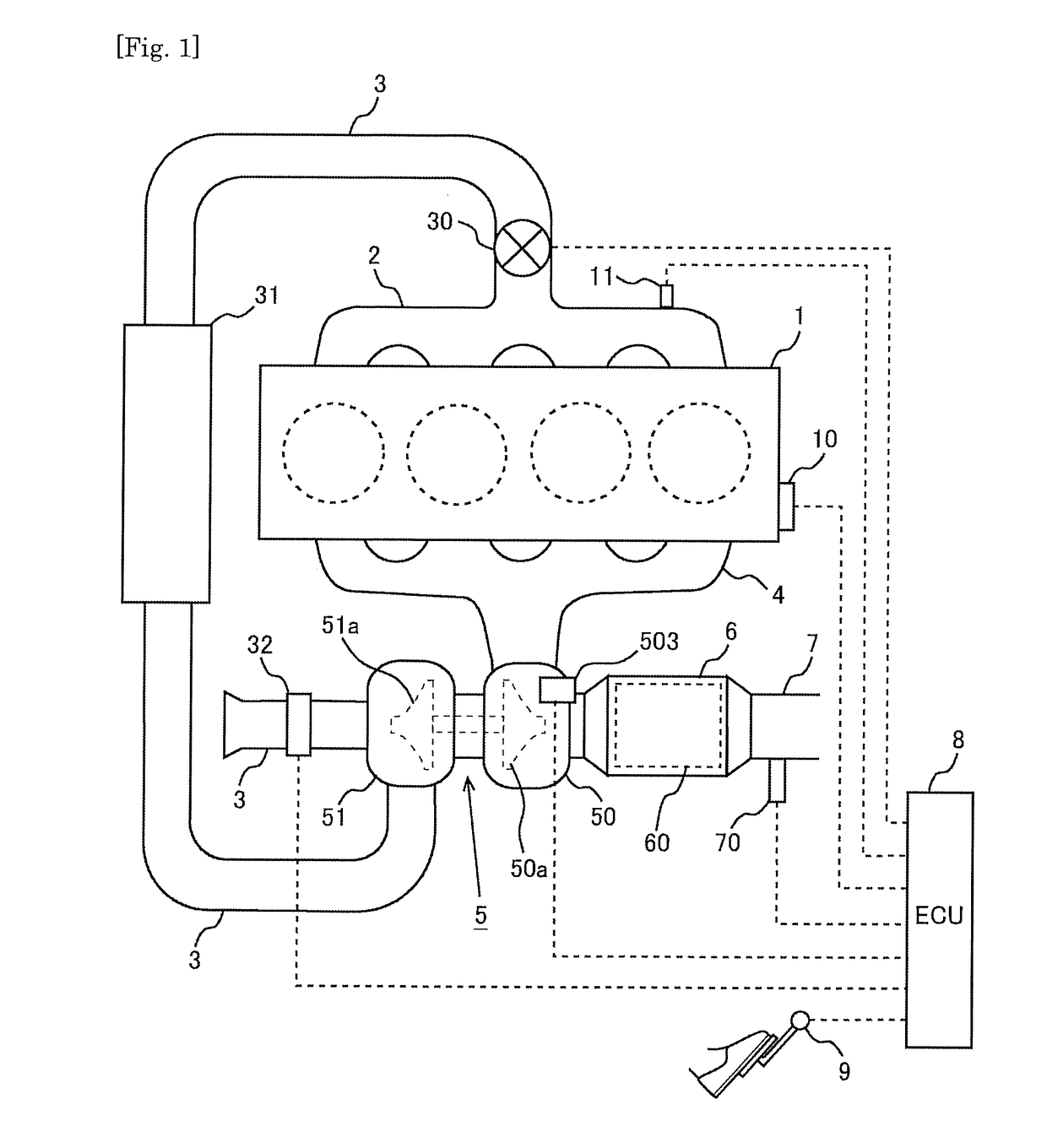
[0030]Reference will be made to a first embodiment of the present disclosure based on FIGS. 1 through 7. FIG. 1 is a view showing the schematic construction of an internal combustion engine to which the present disclosure is applied. The internal combustion engine 1 shown in FIG. 1 is a compression ignition type internal combustion engine (diesel engine) or a spark ignition type internal combustion engine (gasoline engine).

[0031]The internal combustion engine 1 is connected to an intake pipe 3 through an intake manifold 2. In the middle of the intake pipe 3, there is arranged a throttle valve 30 which serves to adjust the channel cross section of the intake pipe 3. A compressor housing 51 of a turbocharger 5 is arranged in the intake pipe 3 at the upstream side of the throttle valve 30. An intercooler 31 is arranged in the intake pipe 3 at a location between the compressor housing 51 and the throttle valve 30.

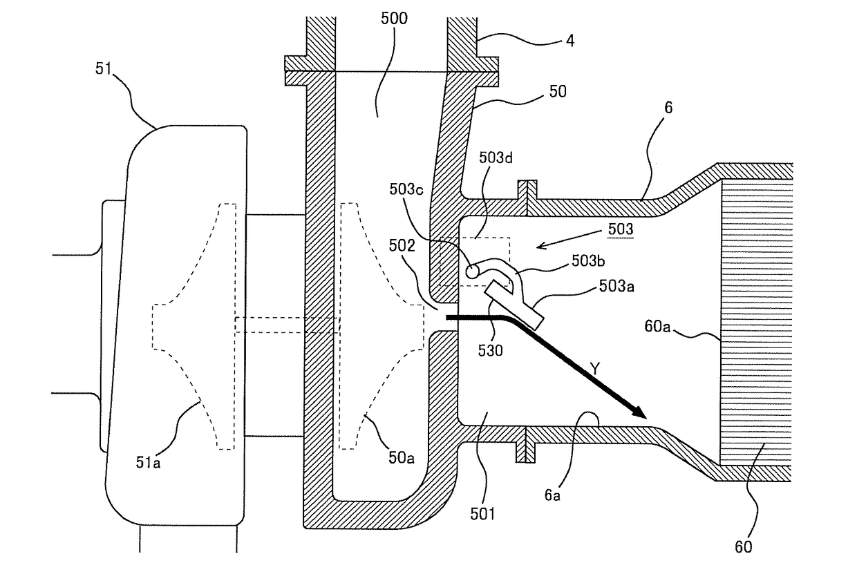
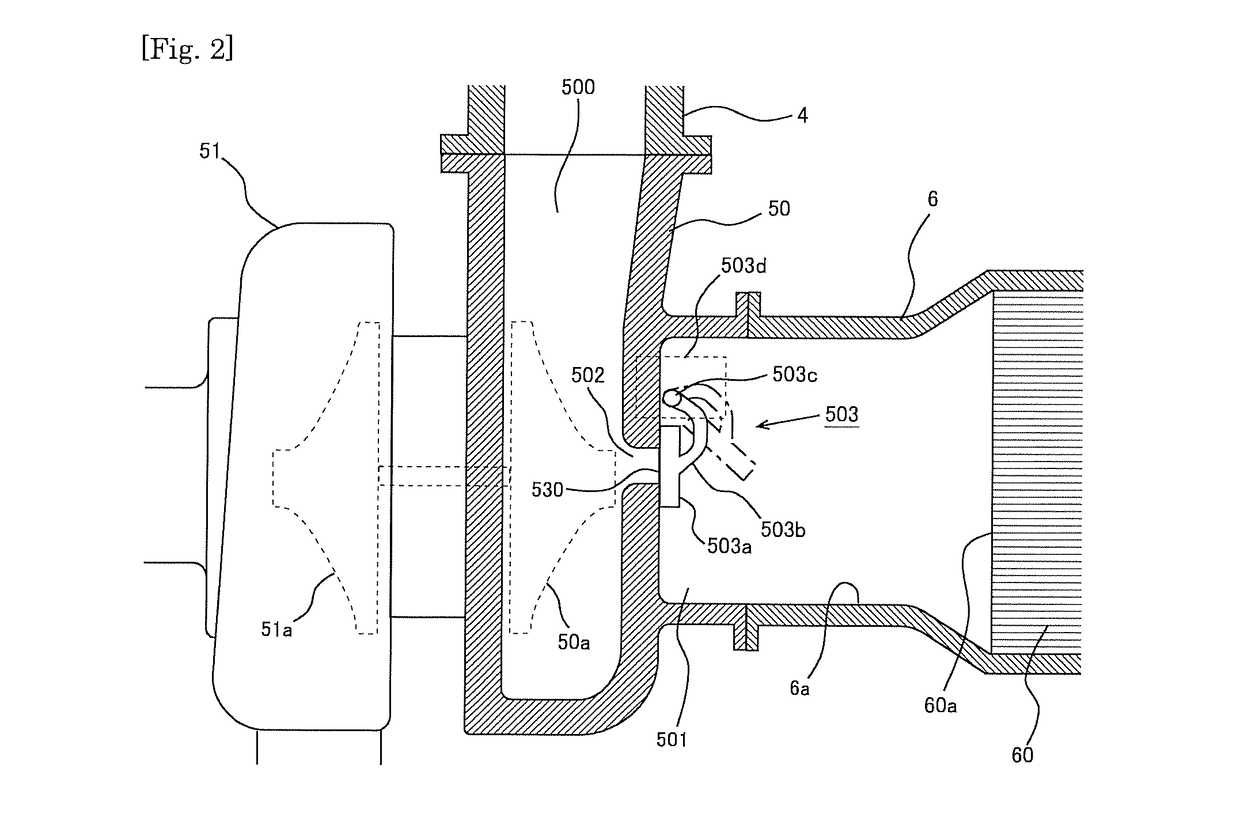
[0032]In addition, the internal combustion engine 1 is connected to a turb...

embodiment 2

[0053]In the above-mentioned first embodiment, the above-mentioned processing routine of FIG. 6 is carried out in a repeated manner during the execution of the fuel cut off processing, and hence, in cases where the temperature of the exhaust gas purification catalyst 60 has changed from a temperature less than the predetermined temperature Tpre to a temperature more than the predetermined temperature Tpre, or from a temperature more than the predetermined temperature Tpre to a temperature less than the predetermined temperature Tpre, in the course of the execution of the fuel cut off processing, the degree of opening Dwgv of the valve body 503a of the waste gate valve 503 will be changed. In contrast to this, the degree of opening Dwgv of the valve body 503a of the waste gate valve 503 during the fuel cut off processing execution may be fixed to a degree of opening corresponding to the temperature Tcat of the exhaust gas purification catalyst 60 at the time of the start of the fuel ...


PUM


Abstract

In a control apparatus applied to an internal combustion engine in which when an opening degree of a valve body of a waste gate valve is less than the predetermined opening degree, the extension line intersects a wall surface of an exhaust passage located upstream of the upstream side end face of the exhaust gas purification catalyst, the control apparatus controls the waste gate valve so that at the time of execution of fuel cut off processing, when the temperature of the exhaust gas purification catalyst is less than a predetermined temperature, the valve body is fully closed, whereas when the temperature of the exhaust gas purification catalyst is not less than the predetermined temperature, the opening degree of the valve body is made to a deterioration suppression opening degree which is larger than when the valve body is fully closed and which is smaller than the predetermined opening degree.

Description

BACKGROUND[0001]Technical Field[0002]The present disclosure relates to a control technology which is applied to an internal combustion engine including an exhaust turbine supercharger (turbocharger) for driving a centrifugal type compressor by using exhaust gas energy, and in particular to a technology to control a waste gate valve attached to the turbocharger.[0003]Description of Background Art[0004]As a supercharger applied to an internal combustion engine, there has been known a turbocharger which is provided with a turbine arranged in an exhaust passage, a compressor arranged in an intake passage, a bypass passage for causing exhaust gas to flow therethrough while bypassing the turbine, and a waste gate valve equipped with a valve body for opening and closing the bypass passage.[0005]A first patent literature discloses an arrangement of an internal combustion engine in which an exhaust gas purification catalyst is arranged in an exhaust passage at a location downstream of a turb...

Claims


Application Information

Patent Timeline
Patent Type & Authority Applications(United States)
IPC IPC(8): F02D41/02F01N13/00F01N3/20F02D41/30F02B37/18
CPCF02D41/024F02D41/3005F01N13/008F01N3/20F02B37/183F01N9/00F02D41/123F02D41/0007F01N2900/1602F02D2200/0802Y02T10/12Y02T10/40
Inventor KIMURA, KOICHINAKAGAWA, NORIHISAHOSOYA, TAKANOBUOKUBO, TAKUYA
Owner TOYOTA JIDOSHA KK
Why Eureka
Try Eureka