Surface mounted electronic component

Active Publication Date: 2006-01-12
TDK CORPARATION
View PDF1 Cites 7 Cited by
  • Summary
  • Abstract
  • Description
  • Claims
  • Application Information

AI Technical Summary

Benefits of technology

[0008] In the present invention, since the radius of curvature of the vertex of the terminal electrode that covers the vertex of the element body is set to a value being 10% or more and 20% or les

Problems solved by technology

As described above, there has been the possibility that such an electronic compone

Method used


Image

  • Surface mounted electronic component
  • Surface mounted electronic component
  • Surface mounted electronic component

Examples


Embodiment Construction

[0016] The preferred embodiment of the present invention will be described below in detail with referring to the accompanying drawings. The same elements, or elements with the same function will be denoted by the same reference symbols in the description, without redundant description.

[0017] In the present embodiment, the present invention is applied to a multilayer inductor.

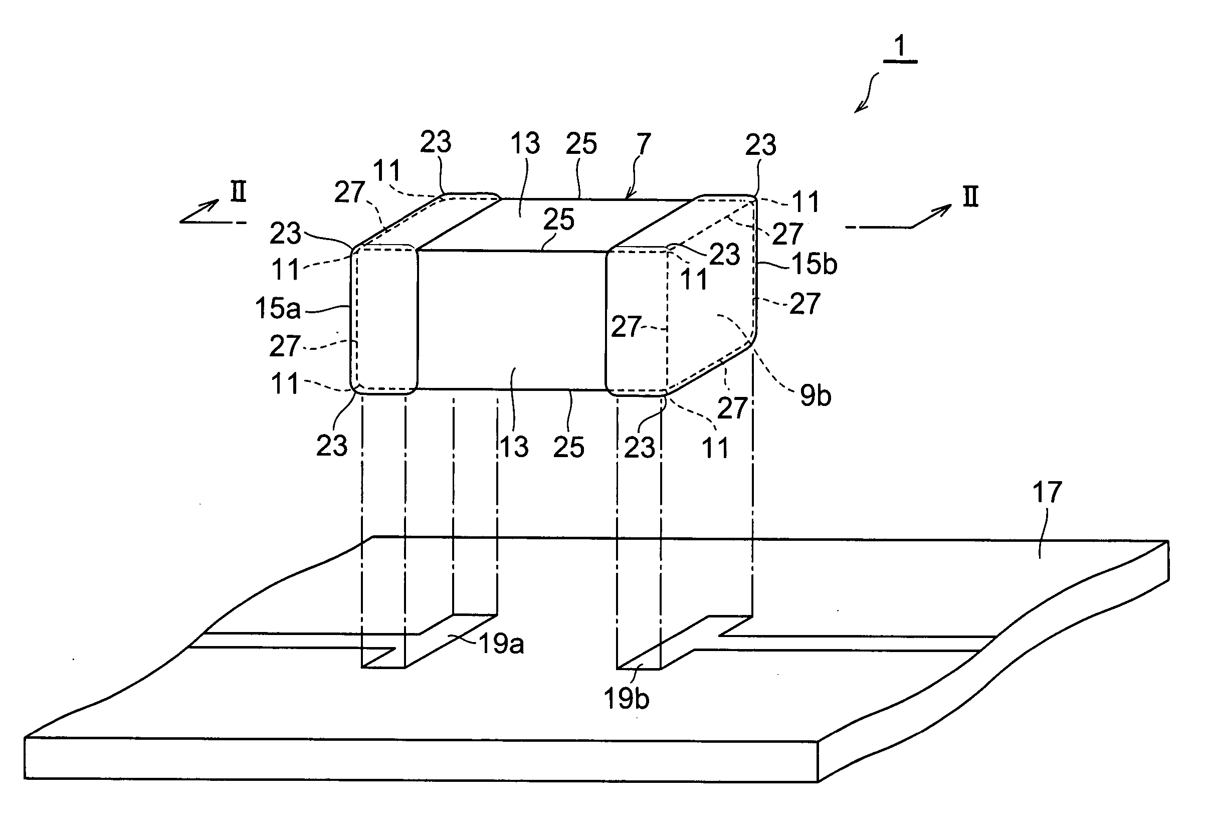
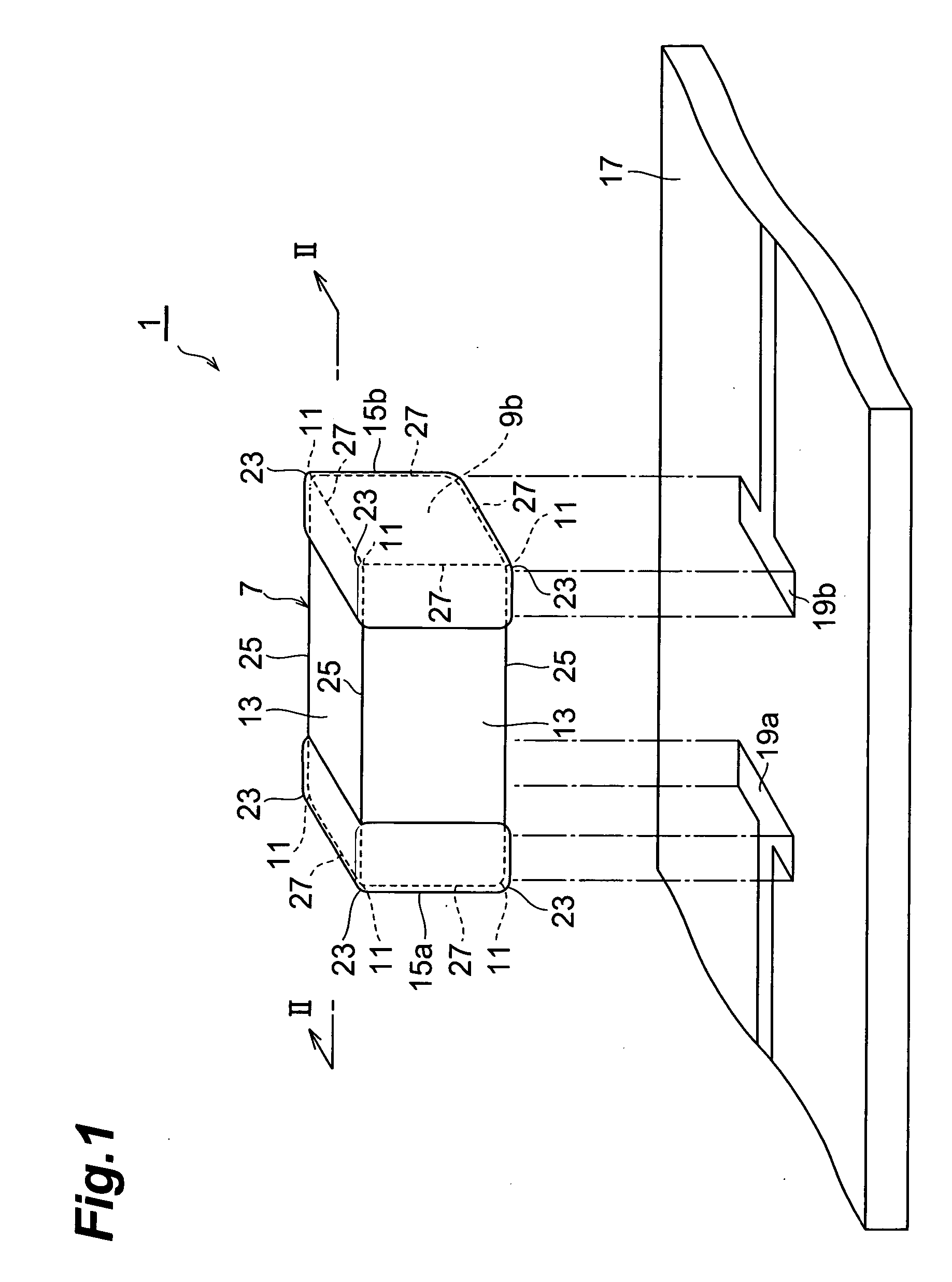
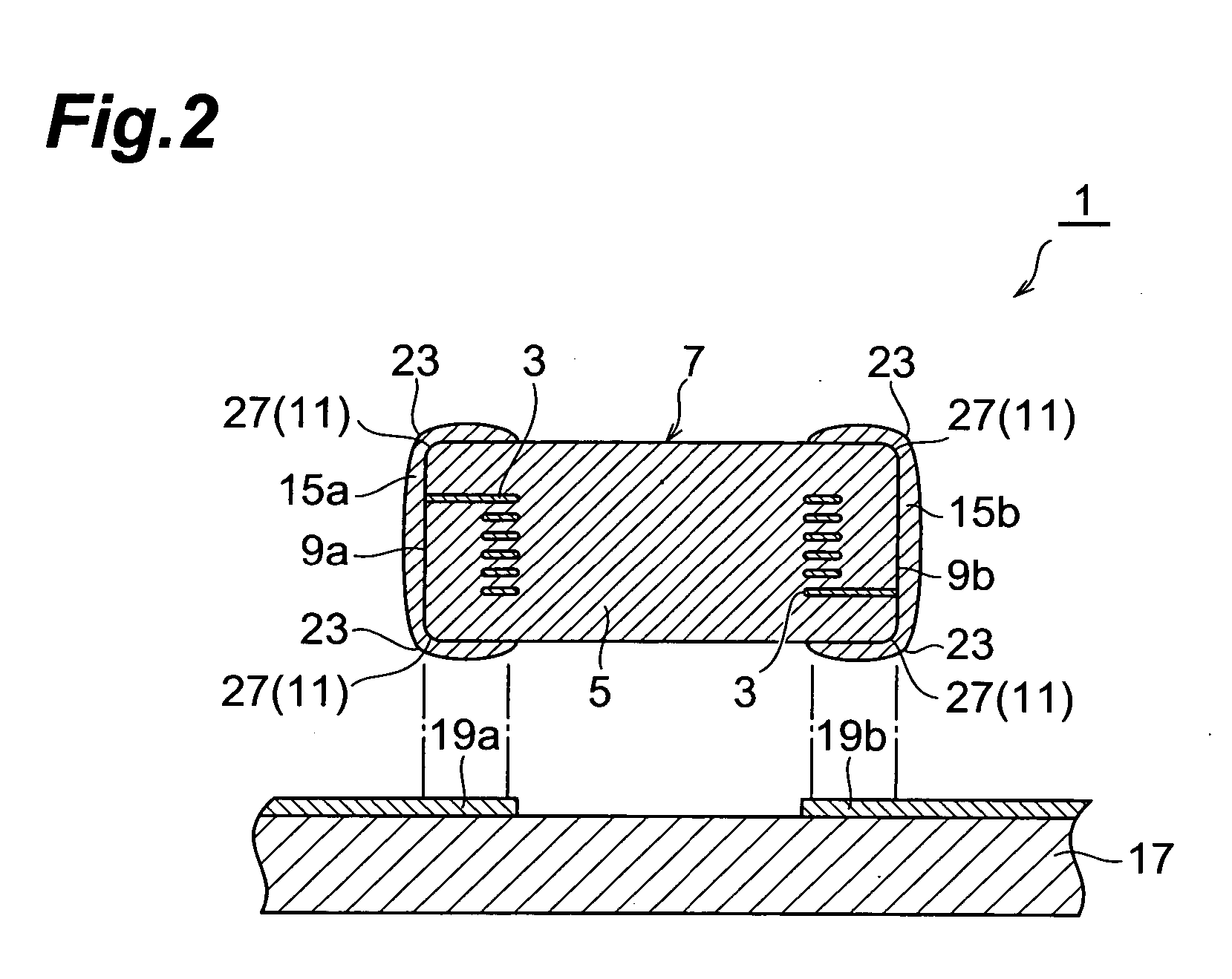
[0018] As shown in FIG. 1 and FIG. 2, a multilayer inductor 1 comprises an element body 7 and terminal electrodes 15a and 15b located on both end faces 9a and 9b in the lengthwise direction of the element body 7. The multilayer inductor 1 is mounted on a mounting substrate 17 for use in such a manner that its lengthwise direction and width direction are parallel to the surface of the mounting substrate 17. The mass of the multilayer inductor 1 is approximately 0.2 mg.

[0019] The element body 7 is a multilayer body composed of a plurality of laminated ceramic layers 5 provided with an internal electrode 3. The ...


PUM

PropertyMeasurementUnit
Fractionaaaaaaaaaa
Fractionaaaaaaaaaa
Fractionaaaaaaaaaa

Abstract

A multilayer inductor has a rectangular parallelepiped element body and its length in the lengthwise direction (L), length in the direction of height (H), and length in the direction of width (W) are L≦0.6 mm, H≦0.3 mm, and W≦0.3 mm, respectively Terminal electrodes are provided so as to cover the vertices of the element body and come round to the side face from the end faces on both sides. The radius of curvature R of the vertex of the terminal electrode is set to a value being 10% or more and 20% or less of H or W.

Description

BACKGROUND OF THE INVENTION [0001] 1. Field of the Invention [0002] The present invention relates to a surface mounted electronic component. [0003] 2. Related Background Art [0004] Recently, there has been a high demand for reduction in size of an electronic component to make an electronic device more compact. Particularly, reduction in size is being developed for a surface mounted electronic component, which is mounted on the surface of a mounting substrate. As the surface mounted electronic component, a multilayer ceramic capacitor having a rectangular parallelepiped ceramic element body and terminal electrodes provided on both ends in the lengthwise direction of the ceramic element body is known. The dimensions of the ceramic element body are 0.6 mm×0.3 mm×0.3 mm. The multilayer ceramic capacitor is an electronic component of so-called 0603 type and its outside dimensions are small and the mass is very light. SUMMARY OF THE INVENTION [0005] By the way, as shown in FIG. 3, a surfa...

Claims


Application Information

Patent Timeline
IPC IPC(8): H01G9/00
CPCH01F17/0013H01F27/292H01G2/065Y10T29/417H05K2201/09154H05K2201/10636H05K3/3442Y02P70/50
Inventor ISHIFUNE, MICHIRUTOZAWA, YOJIANBO, TOSHIYUKISATO, HIDEKAZUKUMAGAI, SHUUMI
Owner TDK CORPARATION
Why Eureka
Try Eureka