Turbomachine for low-temperature applications

a technology of turbines and turbine blades, applied in the direction of liquid fuel engines, dynamo-electric machines, electrical apparatus, etc., can solve the problems of brittle windings, high heat generation, and brittleness of windings, so as to achieve effective prevention of uncontrolled cooling of electric machines and shaft bearings, and ensure sufficient cooling of electric machines.

Inactive Publication Date: 2005-11-10
ATLAS COPCO ENERGAS
View PDF9 Cites 10 Cited by
  • Summary
  • Abstract
  • Description
  • Claims
  • Application Information

AI Technical Summary

Benefits of technology

[0007] It is an object of the present invention to provide a turbomachine having the characteristics described initially, wherein on the one hand, uncontrolled cool-out of the electric machine and the shaft bearings is effectively prevented, and wherein on the other hand, at the same time, sufficient cooling of the electric machine is guaranteed.

Problems solved by technology

Such operation causes significant heat to develop both in the electric machine and in the shaft bearings.
On account of such use, the connection between the machine housing and the stage housing causes intensive heat transport from the electric machine towards the cold interior of the stage housing.
This uncontrolled heat stream cools out the electric machine so much that the material of the windings becomes brittle.
The windings thereby become subject to breakage due to vibrations, and any permanent magnets that are involved become demagnetized and therefore ineffective.
The uncontrolled heat stream can furthermore cool the shaft bearings out very greatly, so that lubricants that are used in them solidify to the point of being unusable.

Method used


Image

  • Turbomachine for low-temperature applications
  • Turbomachine for low-temperature applications
  • Turbomachine for low-temperature applications

Examples


Embodiment Construction

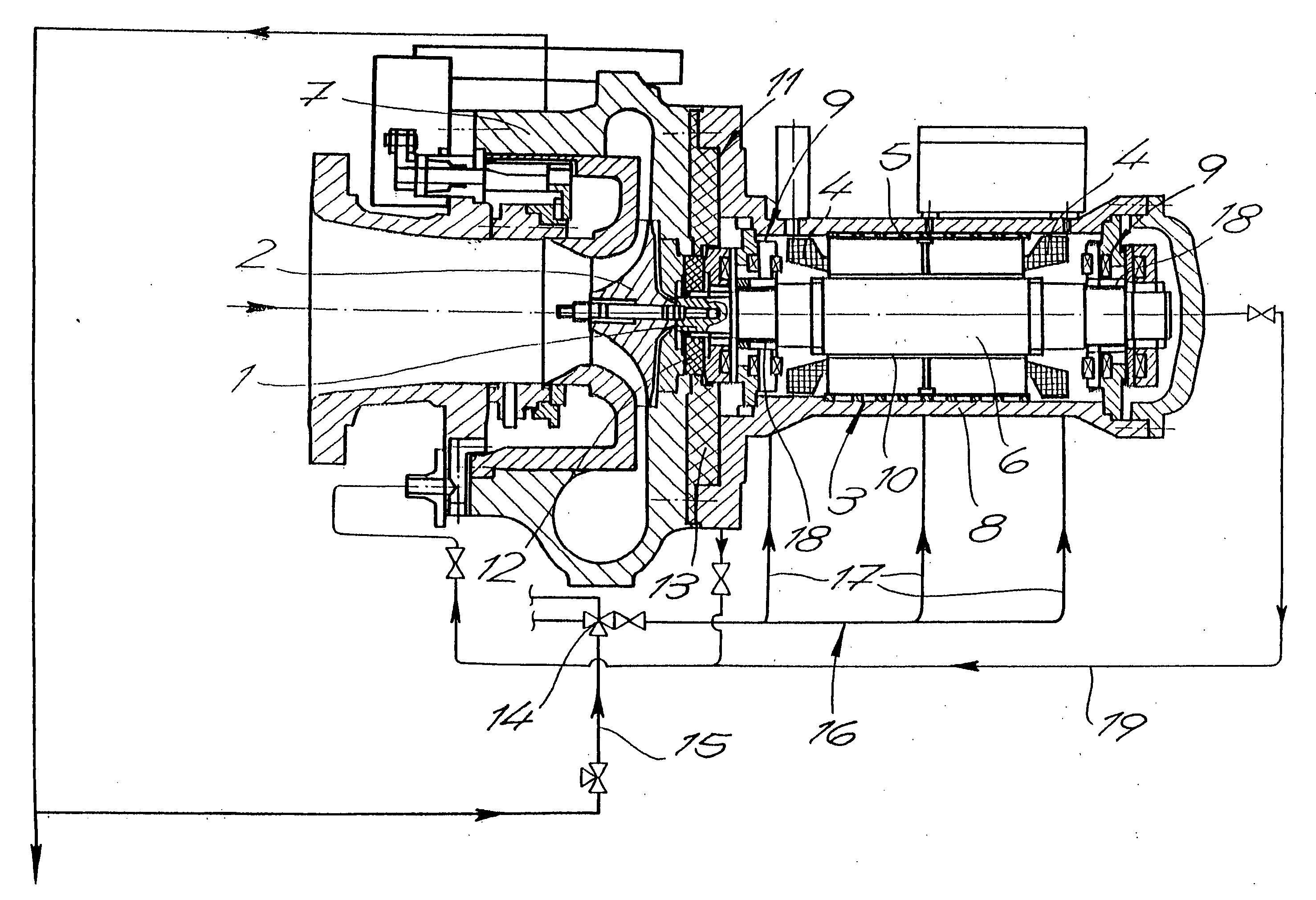
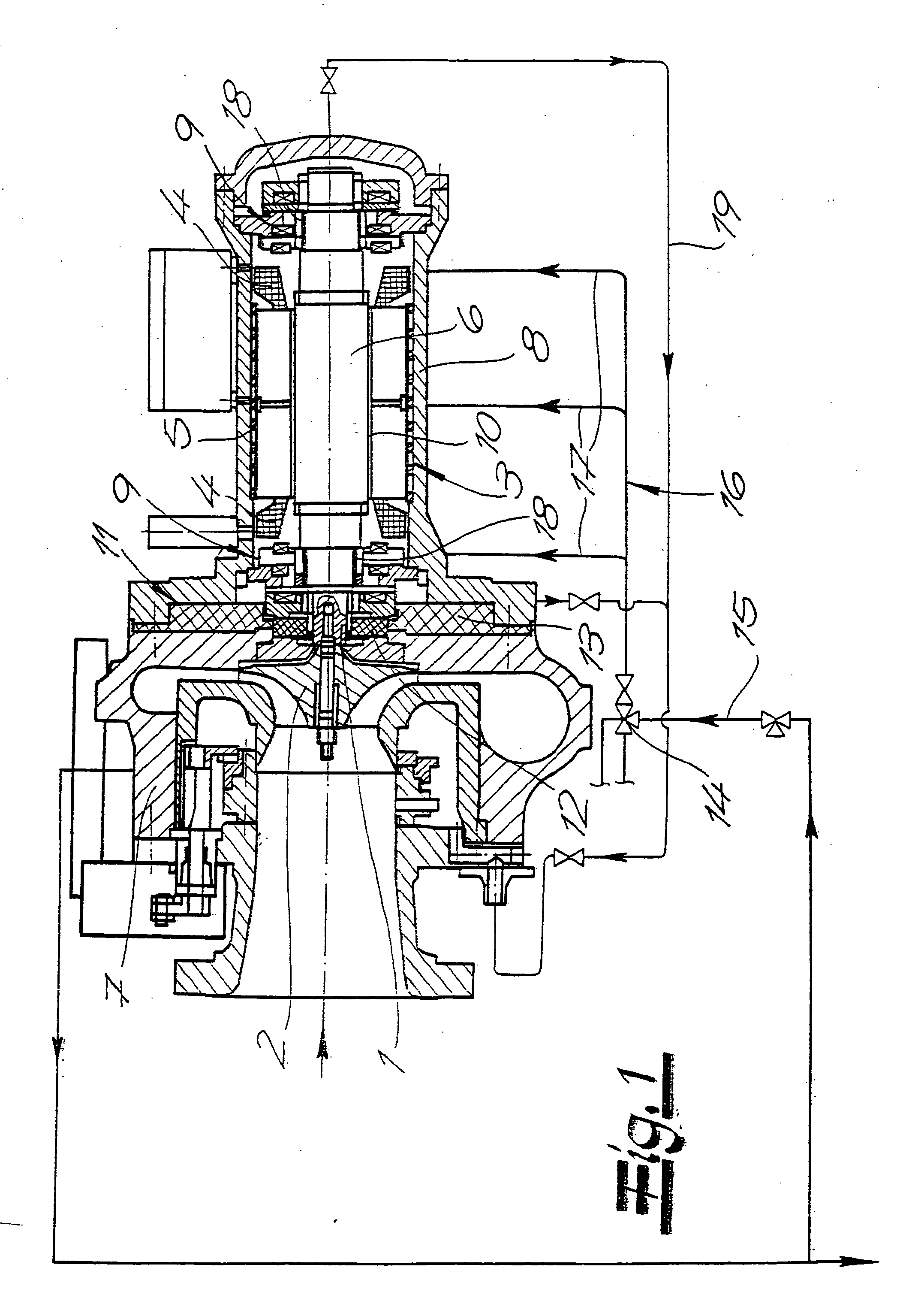
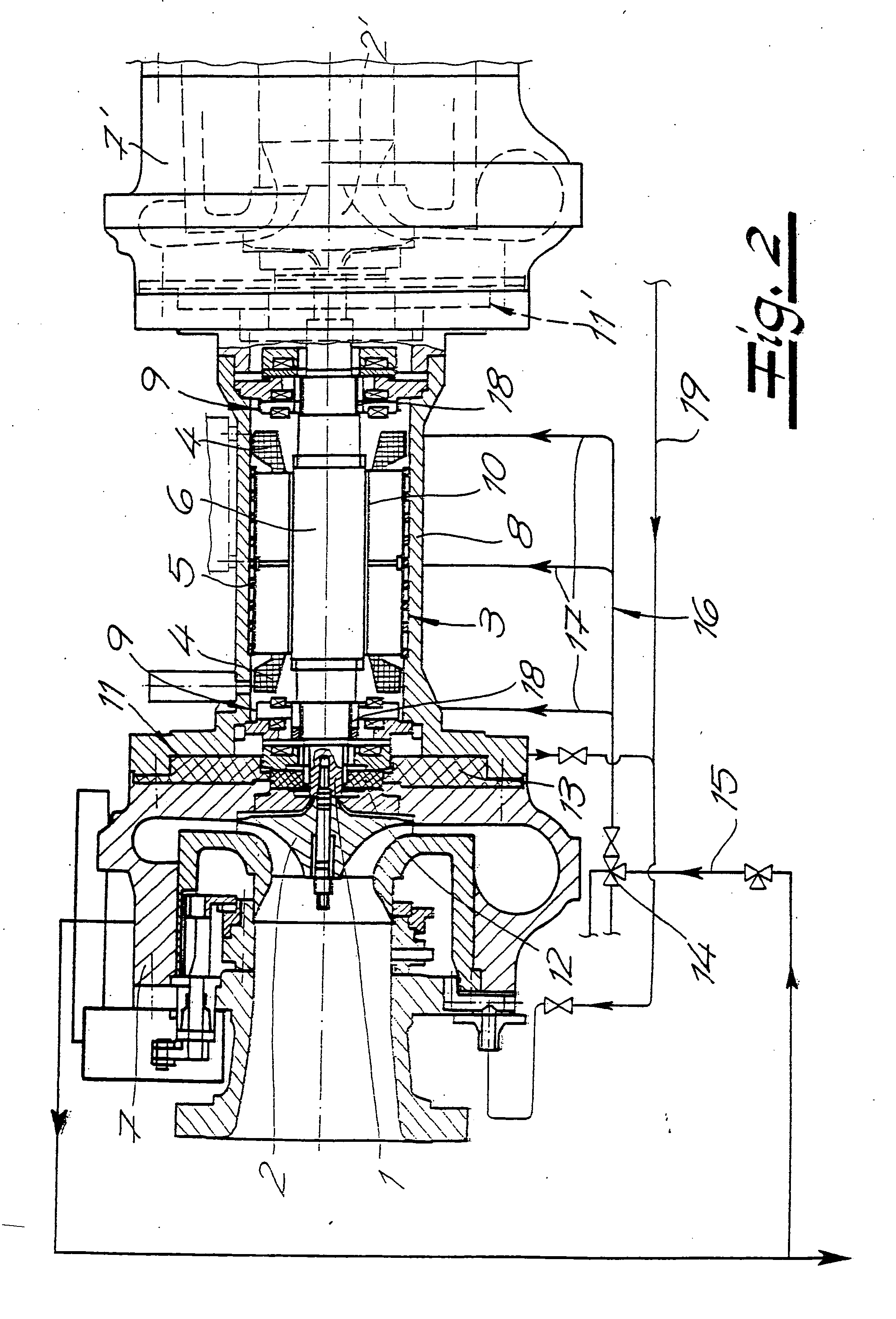
[0018] Referring now to the drawings, an in particular to FIG. 1, a turbomachine for low-temperature applications is shown. It possesses a rotor shaft 1, a rotor disk 2 that is attached at one shaft end of rotor shaft 1, in overhung manner, and an electric machine 3. Electric machine 3 includes a stator 5 that has windings 4, and an electric rotor 6 that is arranged on rotor shaft 1, so that rotor disk 2 and rotor 6 rotate at the same speed of rotation. A stage housing 7 surrounds rotor disk 2 and has connections for a cold gas that flows through stage housing 7. A machine housing 8, in which electric machine 3 and shaft bearings 9 for rotor shaft 1 are arranged, is also provided, in which shaft bearings 9 are located on both sides of rotor 6.

[0019] Machine housing 8 is connected with stage housing 7. Stator 5 is attached on the inside of machine housing 8 and spaced apart from electric rotor 6, forming a ring gap 10. A partition 11 made of insulating material, which thermally sepa...


PUM


Abstract

A turbomachine for low-temperature applications, has a rotor shaft; at least one rotor disk that is arranged in overhung manner at one shaft end of the rotor shaft; an electric machine having a stator having windings, and an electric rotor arranged on the rotor shaft; a stage housing that surrounds the rotor disk and has connections for a cold gas that flows through the stage housing; and a machine housing in which the electric machine and shaft bearings for the rotor shaft are arranged. The machine housing is connected with the stage housing. A partition made of insulating material is arranged between the stage housing and the machine housing, which thermally separates the stage housing from the machine housing. A line provided with a flow-through regulation fitting is connected to the flow path of the cold gas, for branching off an amount-regulated cooling stream, which is passed to the electric machine within the machine housing.

Description

CROSS REFERENCE TO RELATED APPLICATIONS [0001] Applicant claims priority under 35 U.S.C. §119 of German Application No. 10 2004 023 148.6 filed May 7, 2004. BACKGROUND OF THE INVENTION [0002] 1. Field of the Invention [0003] The present invention relates to a turbomachine for low-temperature applications. The turbomachine has a rotor shaft, at least one rotor disk that is arranged in overhung manner at one shaft end of the rotor shaft, an electric machine having a stator having windings, and an electric rotor arranged on the rotor shaft, a stage housing that surrounds the rotor disk and has connections for a cold gas that flows through the stage housing, and a machine housing in which the electric machine and shaft bearings for the rotor shaft are arranged, wherein the machine housing is connected with the stage housing. [0004] 2. The Prior Art [0005] Turbomachines known from practice, having the characteristics described initially, are operated at high speeds of rotation. Such oper...

Claims


Application Information

Patent Timeline
Patent Type & Authority Applications(United States)
IPC IPC(8): F01D15/10F01D25/12F01D25/14F04D29/58
CPCF16C37/005F04D29/584F04D25/06F04D29/5806F04D29/5853F04D29/58F04D29/04
Inventor BOSEN, WERNER
Owner ATLAS COPCO ENERGAS
Why Eureka
Try Eureka