Self-lubricating vertical orientating vibrating wheel structure subjected to counterweight by using liquid

A technology of vertical orientation and vibrating wheels, which is applied in the direction of roads, road repairs, roads, etc., can solve the problems of compact structure and complexity of the exciter cylinder, the inability to find the entry point, the inability to release the heat generated, and the impact on the service life. Achieve the effects of efficient self-lubrication and self-radiation, rapid self-radiation, and saving steel

Active Publication Date: 2015-05-27
合肥永安绿地工程机械有限公司
View PDF6 Cites 11 Cited by
  • Summary
  • Abstract
  • Description
  • Claims
  • Application Information

AI Technical Summary

Problems solved by technology

Although the above-mentioned structure realizes the original design intention of its original vibratory pressure road, however, its defects cannot be underestimated: due to the existence of the eccentric wheel and the transition wheel train, under the high-speed rotation of the vibration motor, the eccentric block and the transition wheel train The gears at the center rotate violently, and the exciting force generated is extremely huge, and it is inevitable that each bearing will start to heat up rapidly
Only relying on tradit...

Method used


Image

  • Self-lubricating vertical orientating vibrating wheel structure subjected to counterweight by using liquid
  • Self-lubricating vertical orientating vibrating wheel structure subjected to counterweight by using liquid
  • Self-lubricating vertical orientating vibrating wheel structure subjected to counterweight by using liquid

Examples


Embodiment Construction

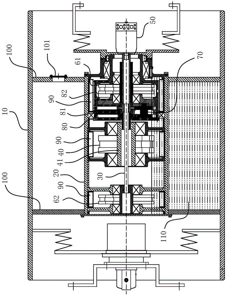
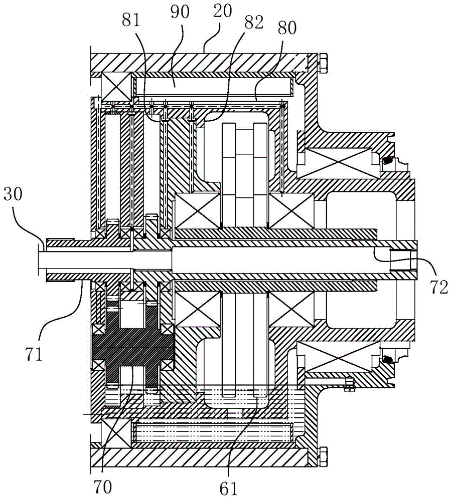
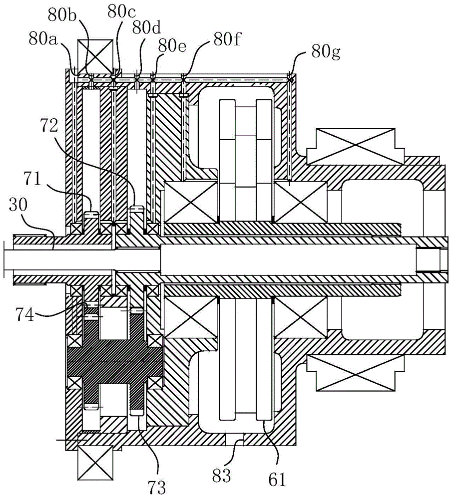
[0042] For ease of understanding, the attached Figure 1-7 Concrete structure and workflow of the present invention are described as follows:

[0043] Concrete installation structure of the present invention, can refer to Figure 1-3 As shown, the vibrating wheel 10 is included as an external steel wheel. The vibrating wheel 10 has a built-in vibrator cylinder 20, and a transmission shaft 30 is fixed in the vibrator cylinder 20 with bearing support, and an external power source 50 is arranged on one side of the transmission shaft 30. Such as figure 1 As shown, the shaft body of the transmission shaft 30 is arranged in sequence from right to left with a first forward rotation eccentric 61 , a direction changing gear set 70 , a reverse rotation eccentric 40 and a second forward rotation eccentric 62 . The second spline shaft gear 72 in the direction-changing gear set 70 receives the power transmission from the external power source 50 on the one hand, and is responsible for tr...


PUM


Abstract

The invention relates to a self-lubricating vertical orientating vibrating wheel structure subjected to counterweight by using a liquid. The self-lubricating vertical orientating vibrating wheel structure comprises a vibrating wheel, a vibration exciter cylinder, a transmission shaft and a cylinder-shaped gear box, wherein a first forwards-rotating eccentric wheel, a backwards-rotating eccentric wheel and a second forwards-rotating eccentric wheel are sequentially arranged along the axial length direction of the transmission shaft, the backwards-rotating eccentric wheel and the first forwards-rotating eccentric wheel are connected with each other through a change gear set; the cylinder-shaped gear box is provided with a gear cavity and an eccentric wheel cavity corresponding to the change gear set and the first forwards-rotating eccentric wheel; the upper end of the cylinder-shaped gear box is provided with a lubricating flow channel, and the lower end of the cylinder-shaped gear box is provided with a liquid outlet; the vibration exciter cylinder is peripherally provided with oil boxes used for rain falling lubrication corresponding to the inner walls of cylinder cavities positioned on the positions of the cylinder-shaped gear box, the second forwards-rotating eccentric wheel and the backwards-rotating eccentric wheel; and the outer wall of the vibration exciter cylinder, the inner wall of the vibrating wheel and ring plates positioned on two ends of the vibrating wheel are encircled to form a sealing cavity used for filling a counterweight liquid together. The self-lubricating vertical orientating vibrating wheel structure disclosed by the invention achieves the sufficient lubrication effect of various bearings and gears inside equipment and can realize the purposes of counterweight and high-efficiency radiation of the vibrating wheel through the counterweight liquid.

Description

technical field [0001] The invention belongs to the field of road roller equipment, and in particular relates to a self-lubricating vertical directional vibrating wheel structure with a liquid counterweight. Background technique [0002] Directional vibratory rollers are machines that use their own gravity and vibration to compact various construction and road construction materials. In highway construction, directional vibratory rollers are widely used because they are most suitable for compacting various non-cohesive soils, crushed stones, crushed stone mixtures, and various asphalt concrete. The structure of the current directional vibratory rollers is composed of a vibrator cylinder and a concentrically arranged transmission shaft fixed therein. The inner chamber of the vibrator cylinder is sequentially arranged in series along the axial direction of the transmission shaft. Eccentric wheel. In the above structure, the eccentric wheel is divided into a forward rotation ...

Claims


Application Information

Patent Timeline
IPC IPC(8): E01C19/28
CPCE01C19/286
Inventor 宋皓崔文平黄方权
Owner 合肥永安绿地工程机械有限公司
Why Eureka
Try Eureka