Device for deep driving of tubes having a large diameter

a technology of deep driving and tubes, which is applied in the direction of caissons, bulkheads/piles, constructions, etc., can solve the problems of increasing limiting the mobility and speed of the excavation machine, and over-consumption of cement mixture, etc., to achieve the effect of improving verticality, simple and cost-effective, and improving the verticality

Active Publication Date: 2015-09-17
SOILMEC
View PDF3 Cites 9 Cited by
  • Summary
  • Abstract
  • Description
  • Claims
  • Application Information

AI Technical Summary

Benefits of technology

[0016]The purpose of the present invention is therefore to make a device for driving in the ground or extracting from the ground tube segments having a large diameter that is able to solve the aforementioned drawbacks of the prior art in a simple, cost-effective and functional manner. The device according to the present invention, working in support of machines for excavating and making piles, is able to drive or extract tube segments having a large diameter in / from the ground through rotation and pushing or pulling, where the tube segments can have lengths equal to at least once the diameter, preferably from 2 to 5 times the diameter.
[0017]In detail, a purpose of the present invention is to make a device for deep driving tubes having a large diameter that makes the driving and extraction steps of the tube faster, at the same time ensuring better verticality.
[0018]Another purpose of the present invention is to make a device for deep driving tubes having a large diameter that is able to reduce the idle times, allowing better exploitation and better productivity of the driving apparatus, also thanks to the possibility of the device supporting many pile driving machines within the same worksite.
[0019]The embodiments of the device according to the invention favor versatility, making an autonomous means in terms of movement and generation of power and capable of moving by its own means in the area of the worksite. The device has the ability to open a part of its frame at any moment to disengage from the driven tube and move with respect to it, to then be repositioned on it and re-engage at a later time to carry out the extraction. Such a later time is decided by the foreman of the worksite based on economic considerations, and may for example be after the steps of insertion of the reinforcement and of concrete casting. During such steps, which are carried out by independent machinery such as a crane and a concrete pump and that do not require the use of the tubing device, the device itself is able to move autonomously and be positioned on the axis of a second pile to perform the driving of the relative guide tube. At a later time, when the steps of casting and of insertion of the reinforcement of the first pile have ended, the tubing device can go back onto the axis of the first pile to extract the casings. Thanks to this special feature the tubing device can serve more than one LDP machine, being able to go back to and move away from the pile, i.e. being able to disengage from a first tube present on the excavation axis of a first LDP machine to engage on a second pile present on the excavation axis of a second LDP machine. This manoeuvre can be carried out at any stage of excavation desired, and consequently it is possible to drastically reduce the inactive times of the tubing device.
[0020]The device according to the invention is advantageous with respect to a generic tubing machine with double “rotary” and continuous helix (CSP), as well as to conventional tubing devices such as casing oscillators or “rotators”. The device according to the invention, indeed, being equipped with its own guiding tower, which is distinct from that of the pile driving machine and is much stronger, makes it possible to install on such a guiding tower a rotary table with much better performances in terms of torque and push-pull with respect to the rotary table that would be installable on the tower of the pile driving machine. Such performances are comparable to or better than that provided by casing oscillators or by “rotators” but, unlike such apparatuses, the device according to the invention makes it possible to drive the tube not through short steps with continuous restarts, but rather through a rotation associated with a continuous thrusting movement, able to be perfectly adjusted, the width of which is determined by the stroke of the rotary table on the guiding tower and is proportional to at least once the diameter of the section of tube to be moved. In particular, the stroke available is preferably greater than the length of the section of tube to be moved. In particular, the rotary table installed on the tower of the tubing device can, during its stroke, go to a height greater than the base of the tower of the machine. In greater detail, the rotary table can slide in front of the guides of the tower of the pile driving machine associated with the tubing device. The presence of the guiding tower ensures better verticality of the tubes during the driving step with respect to casing oscillators and to “rotators”.
[0021]A work method and a series of accessories and constructive solutions facilitate the loading and unloading steps of the tube segments, so as to make the operations safe and fast. The careful study of the work method, associated with the use of such accessories, makes a drilling machine that is versatile and of relatively low weight, and thus cost-effective, suitable for carrying out operations that would require much greater resources if carried out with methods of the prior art.

Problems solved by technology

Of course, this translates into over-consumption of cement mixture and into longer work times in making a partition of known length.
In particular, such friction increases as the length and diameter of the guide tube increase.
This means that above certain diameter and depth values it becomes disadvantageous to make a single machine that performs both the driving of the tube, and the excavation, since such a machine would have to be too big and cost too much.
The use of external apparatuses connected to the excavation machine can allow greater diameters and tubing depths, but it greatly limits the mobility and speed of the excavation machine, as well as increasing costs.
It is difficult for the maximum depth to exceed 30 meters, because for greater depths the machine would have to have a tower that is too long, which would be too heavy for the machine and could cause instability.
On the other hand, it would be necessary to make extremely heavy and bulky machines, but becoming incompatible with all urban works where the spaces available are small.
Moreover, a machine with such a long guiding tower would be difficult to transport.
As the length of the tube increases, the thrust required to drive it also increases, but such a thrust must be limited based on the weight of the machine, which otherwise would tend to lift at the front.
A greater tubed depth implies a greater weight of the battery of tubes and thus requires a greater extraction force of the machine, but also such an extraction force must be limited based on the size of the machine and the resistance of the tracked undercarriage.
The maximum usable diameter for the tube depends on the maximum torque able to be delivered by the lower rotary table and also this must be limited based on the torsional resistance of the tower.
Also in this case, by exceeding certain limit values, the tower would be too heavy.
A drawback of LDP technology consists of the fact that, as the depth reached increases, the duration of the active excavation step, i.e. that for filling the tool, is increasingly short in proportion to the inactive steps of descent and ascent in the excavation.
Another drawback is the fact that the pile is usually excavated with the addition of stabilizing materials that prevent the hole from collapsing, such as bentonite or polymers.
The use of such stabilizers requires rather complex logistics and apparatus to obtain their recovery and recycling, like for example decanting and containment tanks, sieves, grit separators, etc.
These apparatuses are difficult to adapt to use in tight urban spaces or in worksites that extend for many kilometers, requiring continuous movement of the equipment.
When the depth and / or the diameter to be made become high, the torque delivered by the rotary table of the machine is insufficient and external apparatuses become necessary, distinct from the machine, to drive the tube segments by rotation and thrusting up to the desired depth and to extract them at the end of the excavation.
These apparatuses are usually bulky, heavy and expensive.
Therefore, very long cycle times are needed to carry out the excavation.
In particular, the axial movement is limited because the axial stroke available is always less than the length of the piece of tube that is joined.
The aforementioned external apparatuses for driving such tubes have numerous limitations and drawbacks.
Firstly, the cylinders of both types of external apparatuses have limited strokes in the vertical direction, generally of the order of 400-600 millimeters, with consequent limited driving or extraction movements.
Strokes of greater width could lead to interference or collisions between the mobile part of the external driving apparatuses and the tower of the machine.
As a result, in order to drive or extract a few tens of meters of tube a very large number of manoeuvres are needed, each of which comprises the steps of gripping, of translation and of release of the tube, and therefore takes a long time.
A second limitation is due to the fact that the aforementioned external apparatuses, gripping the tube laterally through the upper frame, are not able to completely drive the tube until it is flush with the ground surface.
The tube, therefore, always extends at least partially inside such frames of the external apparatuses and, due to the fact that these frames are monolithic and completely surround the tube, the external apparatuses are fixedly connected to the driven tube, not being able to translate horizontally with respect to it.
This solution is, however, complex and not cost-effective.
A further limitation of casing oscillators and of “rotators” is due to the fact that their hydraulic jaws transmit the torque by clamping the tube on its outer surface, only by friction, and this requires the use of very thick tubes or ones with a double wall to prevent it from becoming oval.
These tubes are particularly heavy and expensive.

Method used


Image

  • Device for deep driving of tubes having a large diameter
  • Device for deep driving of tubes having a large diameter
  • Device for deep driving of tubes having a large diameter

Examples


Embodiment Construction

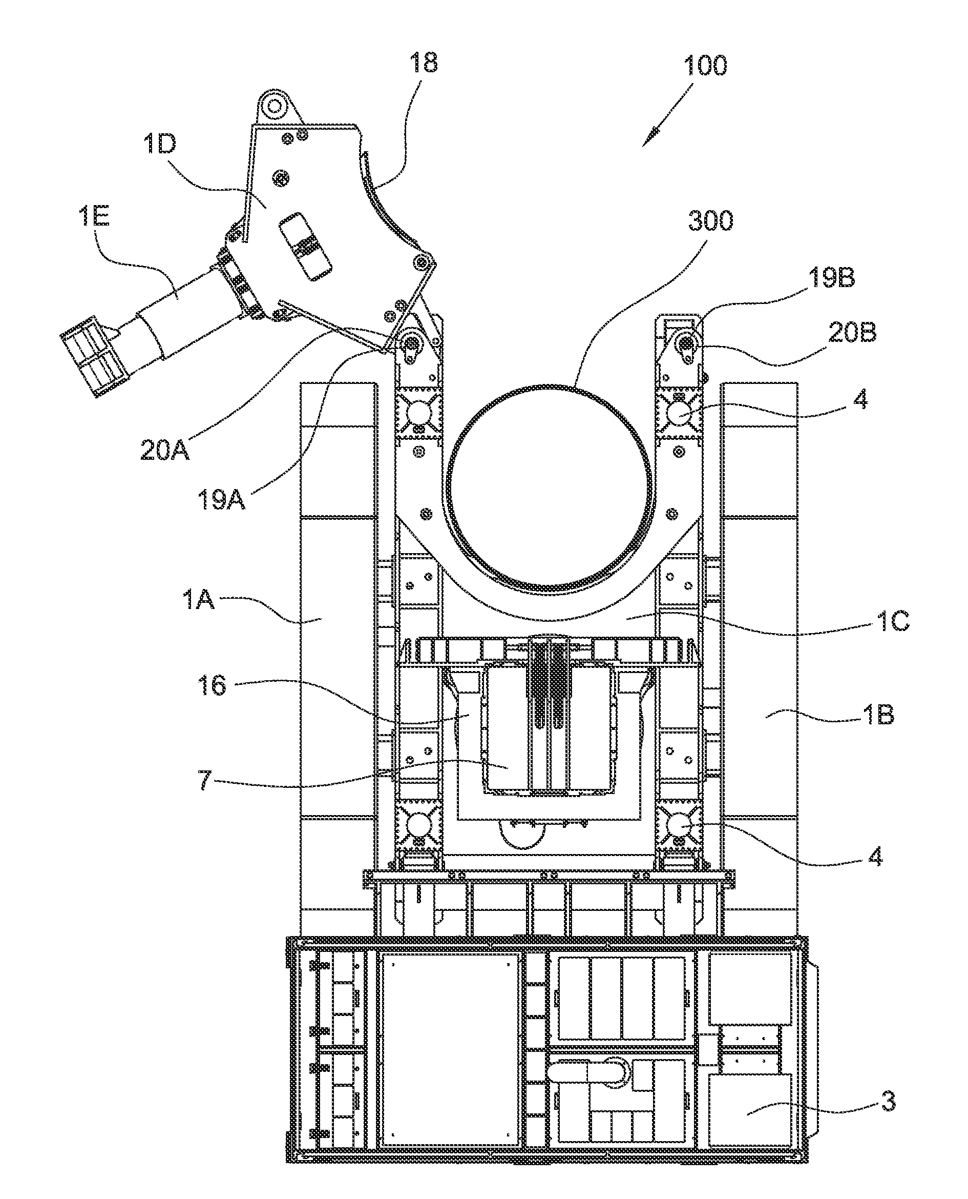
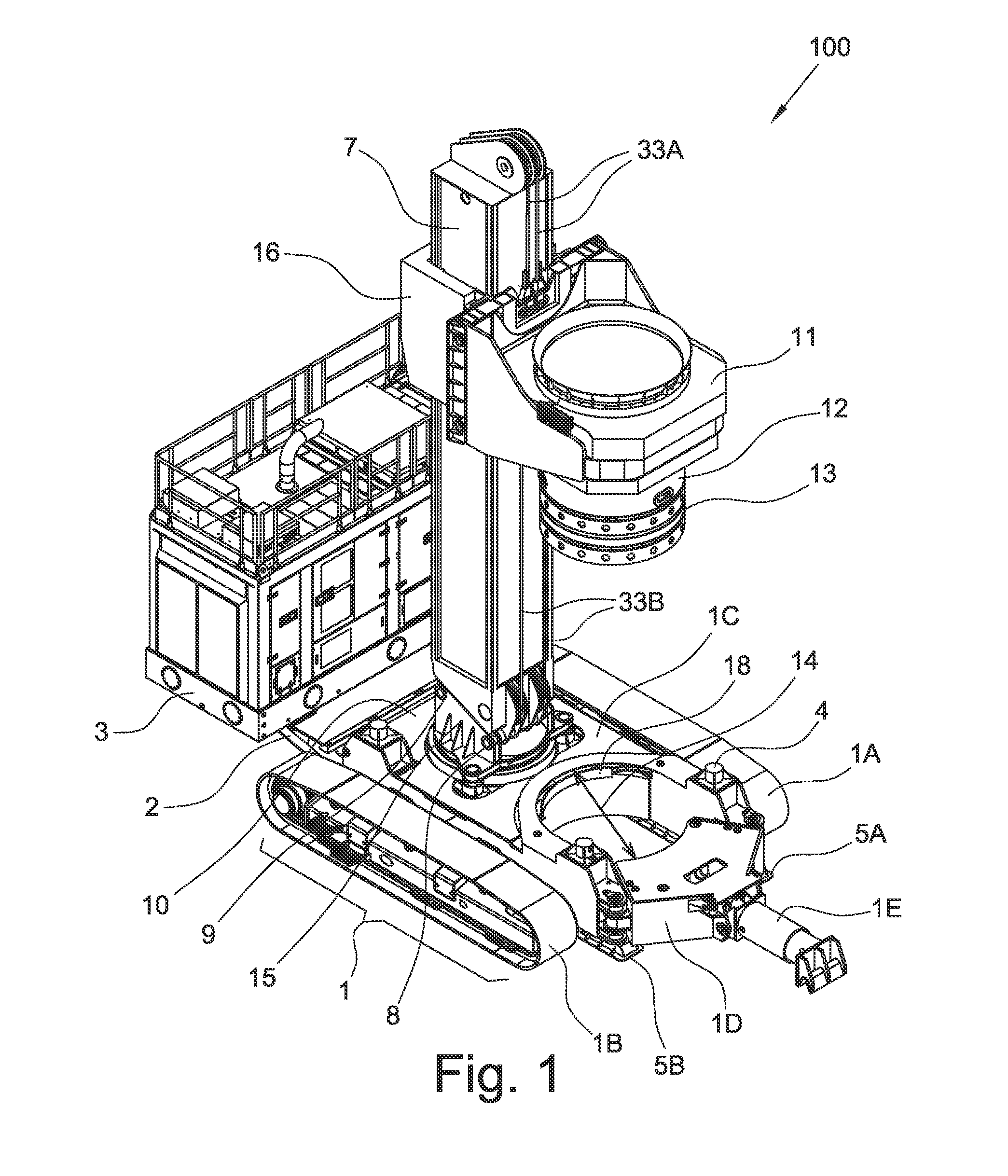
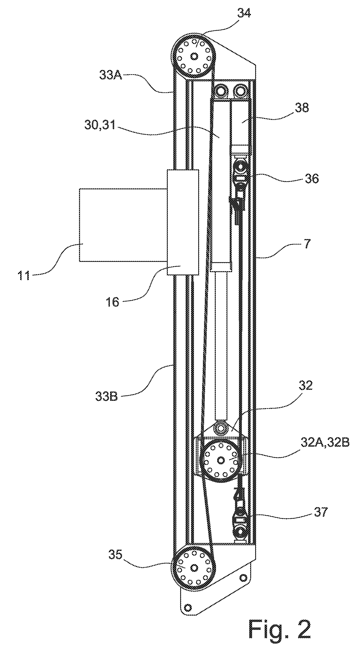
[0030]With reference in particular to FIG. 1, an example embodiment of the device for deep driving tubes having a large diameter according to the present invention, or tubing device, is shown wholly indicated with reference numeral 100. The tubing device 100 substantially consists of:[0031]a base frame or truck 1;[0032]at least one guiding tower 7, fixedly connected to the base frame 1 through a tower support 15;[0033]a unit 10 for moving the at least one guiding tower 7;[0034]a tube operating unit 11, able to slide on each guiding tower 7;[0035]a bracketed support frame 2; and[0036]a power group 3.

[0037]In particular, with respect to a middle vertical plane of the tubing device 100 and in the operative condition of the tubing device 100 itself, the tube operating unit 11, the guiding tower 7 and the base frame 1 can be assembled in a C-shaped configuration in which, due to stability and proportioning issues of the structures, the guiding tower 7 is in a slightly backward position w...


PUM


Abstract

The invention describes a tubing device of the type operatively connectable to an excavation machine and configured to perform an excavation in the ground contained, at least partially, inside at least one tube segment. The tubing device comprises a base frame, at least one guiding tower for the tube segment, operatively connected to the base frame, and a tube operating unit, operatively connected to the guiding tower. The tube operating unit is slidable along the guiding tower and is provided with engaging means capable of both selectively holding the tube segment, and of transmitting a rotary motion and an axial sliding movement to such a tube segment so as to allow the progressive driving in the ground and subsequent extraction from the ground. The axial sliding movement is guided by the guiding tower and the width of such axial sliding movement is determined by the stroke of the tube operating unit on such a guiding tower and is proportional to at least once the diameter of the tube segment.

Description

CROSS-REFERENCE TO RELATED APPLICATIONS[0001]The present application claims the priority of Italian Patent Application No. MI2014A000407, filed Mar. 13, 2014, the contents of which are incorporated herein by reference.FIELD OF THE INVENTION[0002]The present invention refers to a device for driving in the ground or extracting from the ground tube segments having a large diameter.BACKGROUND OF THE INVENTION[0003]In the field of foundations it is often required to have excavations having a large diameter, at great depth and with minimal deviations with respect to their vertical axis. An example of application in which such excavations are required consists of making impermeable partitions carried out through intersecting piles. In these cases the guarantee of actual interpenetration of the primary and secondary piles, closely linked to the verticality of the excavations, is an essential condition to carry out the work correctly. The uncertainty of the verticality of the pile leads to o...

Claims


Application Information

Patent Timeline
Patent Type & Authority Applications(United States)
IPC IPC(8): E02D5/38E02D7/28E02D15/04
CPCE02D5/385E02D7/28E02D15/04E02D5/285E02D5/66E02D7/26E02D11/00E02D2600/30
Inventor DITILLO, ALESSANDROCURIC, JASMINBISERNA, EZIOCASADEI, MARCOGIUNCHEDI, ALESSANDRO
Owner SOILMEC
Why Eureka
Try Eureka