Wind Energy Recovery in the Wheels of Vehicles

a technology of wind energy recovery and vehicle wheels, which is applied in the direction of liquid fuel engines, vessel construction, marine propulsion, etc., can solve the problems of inability to meet the needs of transportation,

Active Publication Date: 2015-09-17
THOMAZIOS KEVIN
View PDF27 Cites 9 Cited by
  • Summary
  • Abstract
  • Description
  • Claims
  • Application Information

AI Technical Summary

Problems solved by technology

Propellers or fans driven by a machine such as a motor, generate thrust by accelerating the air as it moves past the rotating blades, thus causing a pressure differential resulting in a net force.
Aside from this application, slipstream is considered a by-product of the thrust generation process and is largely ignored and unused.
However, dependency on acceleration and deceleration for energy is both unpredictable and inconsistent because a vehicle system cannot predict when the driver will be accelerating or braking.
Thus, the amount of energy collected is inconsistent.
Owners and drivers are unable to reliably predict how much energy their vehicles will have for their required range and payload combinations.
Vehicle manufacturers using this approach for wheel energy recovery face a complex solution that does little to improve the range and payload issues currently facing state-of-the-art electric vehicles.
It suffers from the same fundamental problem as does Chien's invention—it causes even more significant drag on the vehicle which makes energy recovery performance marginal.
Furthermore, the wind actuated component is required to be installed on the external hub of a vehicle's wheels which would expose the component to the curb during parking events and damage to the component becomes a high probability event.
The extensive ducting requires significant volume within the vehicle effectively reducing useful space and payload.
The single generator, with yet its own fan, leaves the vehicle vulnerable.
However, Penev does not address the significant issue of counter-electromotive force or back-e.m.f.—as the wheel rotates, the rotor and stator in the wheel generator require energy to overcome the electromagnetic forces resisting rotation which can only come from the energy supplied by the motor.
If the motor is not boosted or compensated for this energy, this clearly leads to the conclusion that the net rotation speeds of the wheel and its wheel fan would be lower than it would be without the wheel generator, thus leading to lower net energy recovery.
Such a system, because of the unpredictable nature of ambient wind, is unable to produce consistent and predictable energy recovery.
The requirement that the wheel rims be of large diameter and the use of low profile tires places severe restrictions on the use of such a scheme in electric vehicles.
However, upon further detailed inspection of the reference specification, it is clearly evident that the specification is fundamentally flawed.
Sarwin has failed to provide a structure whereby the fan generating the wind energy is separate and independent from the fan recovering the wind energy.
The wheel is expected to both generate and capture wind energy simultaneously which is clearly impossible.
Furthermore, no means for motoring the wheel has been provided while it is generating.

Method used


Image

  • Wind Energy Recovery in the Wheels of Vehicles
  • Wind Energy Recovery in the Wheels of Vehicles
  • Wind Energy Recovery in the Wheels of Vehicles

Examples


first embodiment

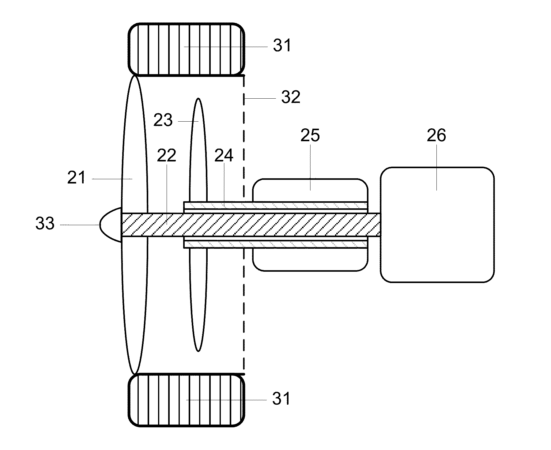
Advantages—FIGS. 1A, 1B, 1C

[0036]From the descriptions of configuration and operation, the following general advantages of the first embodiment are evident:

[0037](a) The absence of gears, also known as direct drive, reduces mechanical losses typically associated with gears.

[0038](b) The load on motor 26 is reduced without gearing, allowing motor 26 to output more rotational energy per given unit of input energy thereby increasing efficiency of the motoring section. Increased efficiency of the motoring section improves the production of slipstream, resulting in the improved efficiency of slipstream energy recovery.

[0039](c) The absence of gears reduces the overall inertia of the generating section, thereby improving the efficiency of the generating section.

[0040](d) The use of concentric rotatable shafts reduces the lengths and weights of the shafts, as compared to non-concentric shafts, thus enabling a more compact embodiment and a more attractive commercial implementation.

[0041](e)...

embodiment 2

Alternative Embodiment 2
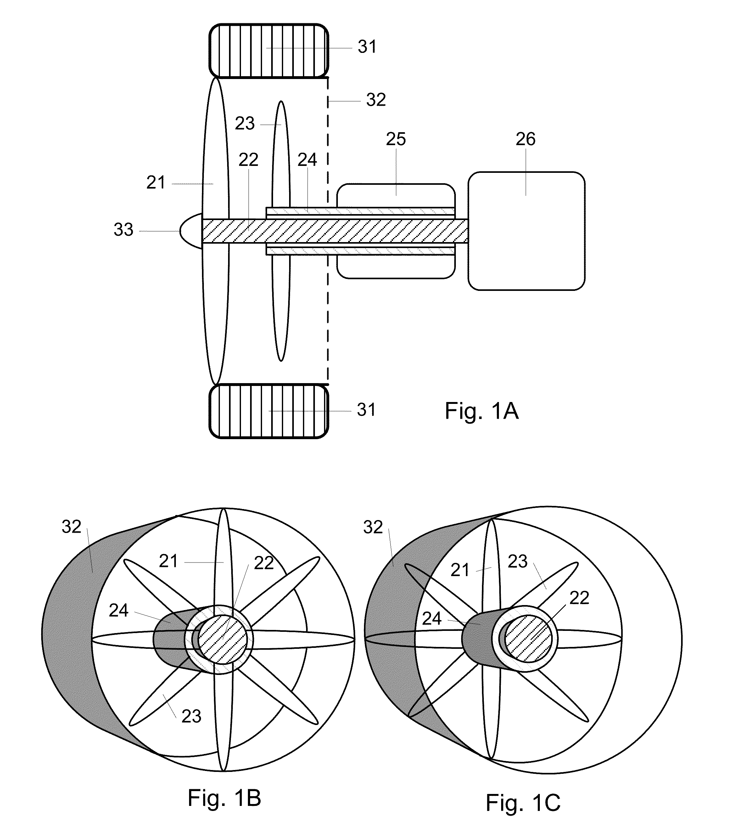
Advantages—FIG. 2

[0055]The advantage of this embodiment over the first embodiment is the flexibility in the configuration enabled by the of use gears thereby allowing for generator 25 to be situated unaligned from generating shaft 24. Generator 25 can now be more easily disassembled and even removed entirely for maintenance and repair. Additionally, for the purposes of product development, those skilled in the art will be able to more conveniently experiment with different generators by simply removing generator 25 and its generating pinion 28. Commercial-off-the-shelf generators can be used instead of custom made generators that would have to fit the specific diameter of generating shaft 24, as in the case of the embodiment of FIG. 1A.

Alternative Embodiment 3

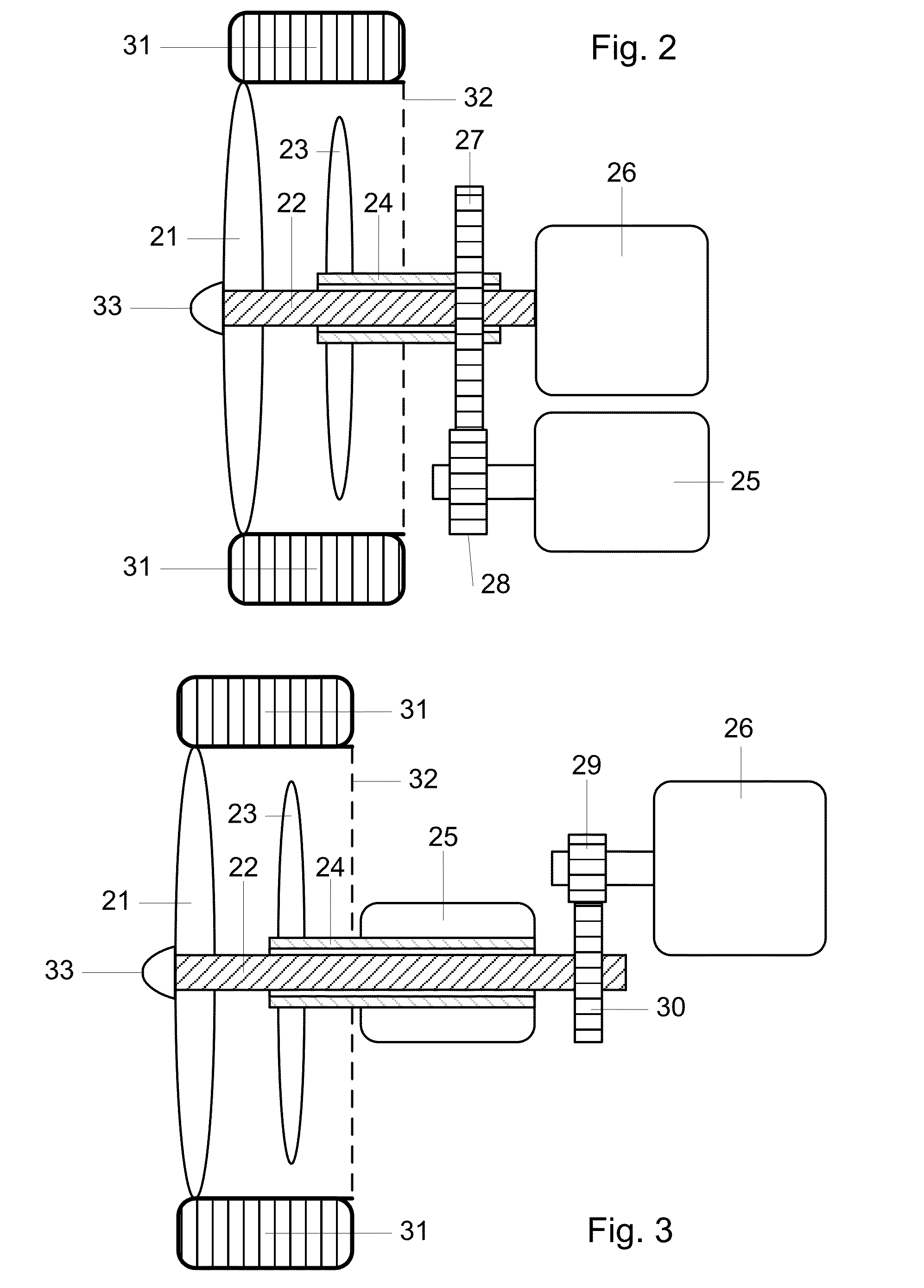
Configuration—FIG. 3

[0056]The embodiment of FIG. 3 illustrates an alternative to FIG. 1A by the possible use of gearing with motor 26. A motoring gear 30 is mounted towards the rear of motoring shaft 22....

embodiment 3

Alternative Embodiment 3

Advantages—FIG. 3

[0058]The advantage of this embodiment over the first embodiment is the flexibility in the configuration enabled by the use of gears thereby allowing for motor 26 to be situated unaligned from motoring shaft 22. Motor 26 can now be more easily disassembled and even removed entirely for maintenance and repair. Additionally, for the purposes of product development, those skilled in the art will be able to more conveniently experiment with different motors by simply removing motor 26 and its motoring pinion 29. Commercial-off-the-shelf motors can be used instead of custom made motors that would have to fit the specific diameter of motoring shaft 22, as in the case of the first embodiment of FIG. 1A.

Alternative Embodiment 4

Configuration—FIG. 4

[0059]The embodiment of FIG. 4 illustrates an alternative to FIG. 1A by having both motor 26 and generator 25 geared as previously described individually in alternative embodiments 2 and 3.

Alternative Embodi...


PUM


Abstract

One embodiment of an apparatus for wheel slipstream energy recovery in wheeled vehicles comprising a plurality of wheel spokes (21) of a wheel attached to a rotatable motoring shaft (22) which in turn is connected to a motor (26) and a generating propeller (23) attached to a rotatable generating shaft (24) which in turn is connected to a generator (25). Operation of the motor (26) results in the motoring propeller (21) to rotate and generate an accelerating slipstream towards the generating propeller (23) which results in the generator (25) rotating to convert recovered rotational energy into other forms of useable energy. The motor (26) may be an electric motor or an internal combustion engine. The generator (25) output is available for charging batteries or powering electrical loads in either electric or conventional vehicles. Both motor (26) and generator (25) are motoring and generating simultaneously.

Description

CROSS REFERENCE TO RELATED APPLICATION[0001]This application is a CIP of Ser. No. 13 / 645,468, filed 2012 Oct. 4 by the present inventor, which is incorporated by reference.BACKGROUNDDescription of Prior Art[0002]The following is a tabulation of prior art that presently appears most relevant:Primary CPC,Issue DatePatenteeU.S. Class / SubU.S. PatentsPatent Number6,765,324 B12004ChienH02K 7 / 02, 310 / 75 CJul. 207,552,787 B12009WilliamsB60K 1 / 00, 180 / 65.51Jun. 307,624,830 B12009WilliamsB60K 6 / 00, 180 / 165Dec. 17,679,210 B22010ZhuB60K 1 / 00, 290 / 55Mar. 168,172,022 B22012SchneidewindB60K 6 / 10, 180 / 165May 88,579,054 B22013KnickerbockerB60K 16 / 00, 180 / 2.2Nov. 128,646,550 B22014PenevB60K 16 / 00, 180 / 2.2Feb. 119,022,150 B22015CunicoB60L 11 / 1809,May 5180 / 2.2U.S. Patent Application PublicationsPublication Nr.2010 / 0026009 A12010SarwinF03D 9 / 00, 290 / 55Feb. 4[0003]Propellers or fans driven by a machine such as a motor, generate thrust by accelerating the air as it moves past the rotating blades, thus cau...

Claims


Application Information

Patent Timeline
Patent Type & Authority Applications(United States)
IPC IPC(8): F03D1/02F03D9/00
CPCF03D9/002F03D1/025F03D9/00F05B2220/602F05B2240/941F03D9/25Y02E10/728F03D9/32F03D15/20F03D15/10B60K16/00Y02E10/72F03D13/10
Inventor THOMAZIOS, KEVIN
Owner THOMAZIOS KEVIN
Why Eureka
Try Eureka