

Measurement apparatus and measurement method
a technology of measurement apparatus and measurement method, which is applied in the direction of measurement devices, instruments, scientific instruments, etc., can solve the problems of long measurement time of the above-mentioned measurement apparatus, and the cost of devices such as multi-angle stages configured to change the angle of a placed object, so as to achieve high accuracy and facilitate measuremen
- Summary
- Abstract
- Description
- Claims
- Application Information
AI Technical Summary
Benefits of technology
Problems solved by technology
Method used
Image

Examples
first embodiment
[0025][Apparatus Arrangement]
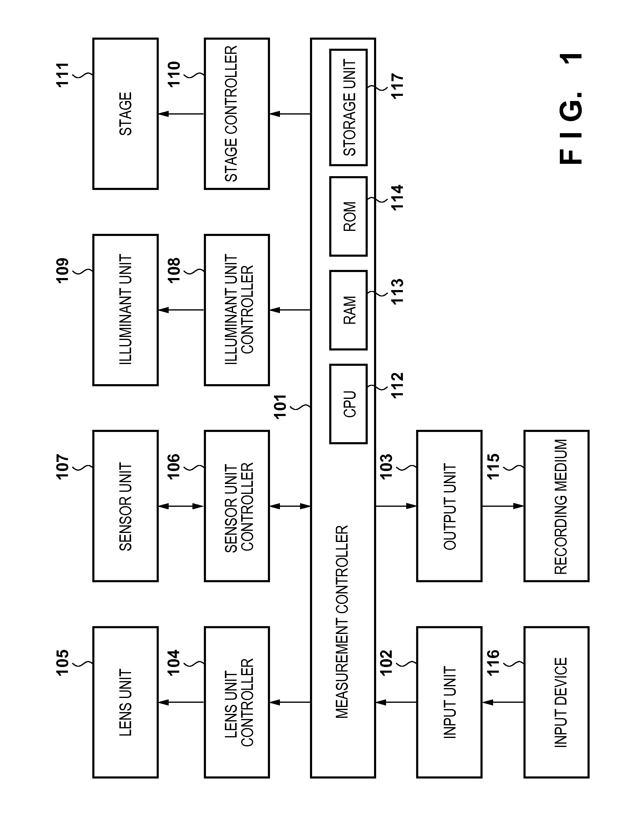
[0026]FIG. 1 is a block diagram showing the arrangement of a measurement apparatus according to the first embodiment. The measurement apparatus according to this embodiment acquires the multi-angular reflectance property of an object. In FIG. 1, a measurement controller 101 performs a series of control operations to send necessary control signals to a lens unit controller 104, a sensor unit controller 106, and an illuminant unit controller 108, and output a multi-angular reflectance property from an output unit 103.
[0027]A microprocessor (CPU) 112 of the measurement controller 101 executes an operating system (OS) stored in a read only memory (ROM) 114. When a measurement start instruction is input from an input unit 102, the CPU 112 loads, to a random access memory (RAM) 113, a measurement program stored in advance in the ROM 114 or a storage unit 117 such as a hard disk drive (HDD), and executes the measurement program. Details of measurement processin...
second embodiment
[0087]The second embodiment according to the present invention will be described below. The first embodiment has described a method of controlling the diaphragm 401 of the lens unit 105 in order to change the aperture angle β serving as a geometric condition of rays passing through the lens unit 105. In the second embodiment, the aperture angle β is changed by changing even the distance between a lens unit 105 and an object 201 to be measured, in addition to a diaphragm 401 of the lens unit 105. Note that the arrangement of a measurement apparatus and a basic processing sequence in the second embodiment are the same as those in the first embodiment, thus a description thereof will not be repeated, and only a difference from the first embodiment will be explained below.
[0088][Lens Unit Controller]
[0089]FIG. 15 is a block diagram showing the arrangement of a lens unit controller 104 according to the second embodiment. The lens unit controller 104 according to the second embodiment inc...
third embodiment
[0097]The third embodiment according to the present invention will be described below. In the third embodiment, higher-accuracy two-dimensional distribution data of reflectances can be acquired by capturing an image that is in focus at higher accuracy in the full angle of view.
[0098][Optical Arrangement]
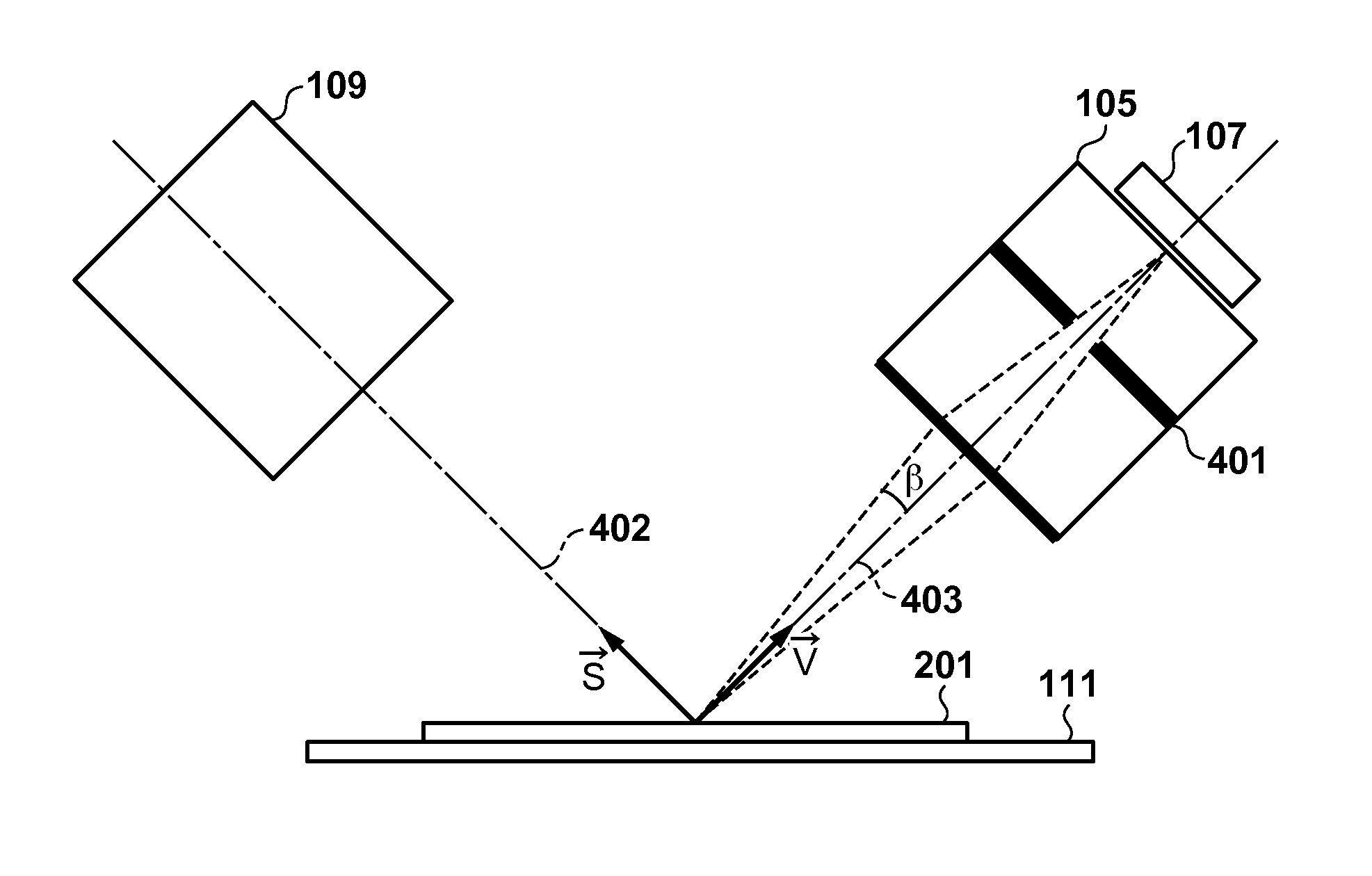
[0099]FIG. 11 shows the optical arrangement of respective units in a measurement apparatus according to the third embodiment. As shown in FIG. 11, the optical arrangement according to the third embodiment is different from the optical arrangement shown in FIG. 4 in that a sensor unit 107 has a tilt with respect to a lens unit 105. By inclining the lens unit 105 in this manner, the focus on the surface of an object 201 to be measured can be adjusted at high accuracy. The tilt angle of the sensor unit 107 complies with a well-known Scheimpflug principle. Although a detailed description will be omitted, the entire surface of the object 201 is in focus by setting the light receiving surf...
PUM
| Property | Measurement | Unit |
|---|---|---|
| multi-angular reflectance property | aaaaa | aaaaa |
| aperture diameter | aaaaa | aaaaa |
| angle | aaaaa | aaaaa |
Abstract
Description
Claims
Application Information