Small hole diameter automatic measuring apparatus, small hole diameter measurement method, and shower plate manufacturing method

a technology of automatic measuring apparatus and small hole diameter, which is applied in the direction of fluid tightness measurement, instruments, other domestic articles, etc., can solve the problems of inability to accurately calculate the effective cross-sectional area a of the small hole, the flow meter itself is complicated, and the measurement of the diameter of the small hole cannot be performed quickly and efficiently, so as to achieve the effect of improving accuracy, reducing labor intensity and reducing labor intensity

Active Publication Date: 2007-05-22
FUJIKIN INC +1
View PDF14 Cites 7 Cited by
  • Summary
  • Abstract
  • Description
  • Claims
  • Application Information

AI Technical Summary

Benefits of technology

[0025]In other words, the primary object of the present invention is to provide a small hole diameter automatic measurement system for a plate in which the diameters of a plurality of small holes formed in a plate can be quickly and accurately measured (or detected), an automatic judgment can be made as to whether or not the detected small hole diameters (or effective cross-sectional areas) are within a permissible range, and the judgment results can be transmitted in real-time to an arbitrary location.
[0054]In the present invention, a plate is placed on a plate carrier that is free to rotate, and a test probe which is supported above this plate carrier so that this test probe can move in the horizontal direction is lowered toward the fluid inlet side of specified small holes in the plate from above, and the tip end of this test probe presses against the upper surface on the fluid inlet side of the small holes in an air-tight manner. Accordingly, the tip end of the test probe can be automatically connected to the fluid inlet side of the respective small holes in the plate in accordance with a predetermined specified program, and the measurement of the diameters of the small holes can be performed more efficiently.
[0055]Furthermore, in the present invention, since a construction that uses an automatic pressure control device and a thermal quantity type mass flow controller having extensive records of use in fluid flow meters is employed, the flow rate of the fluid flowing through the small holes can be measured quickly and accurately.
[0056]Furthermore, in the present invention, the diameter of the small holes (effective cross-sectional area of the small holes) is calculated using the relational formula of the “small hole cross-sectional area, Cv value and small hole contraction coefficient αo,” which has a long record of use in the field of fluid devices. Accordingly, the diameter of the small holes (effective cross-sectional area of the small holes) can be measured with a higher degree of precision. More specifically, in the present invention, the focus is on the effective cross-sectional area of the small holes determined from the Cv value of the small holes and the cross-sectional area A, and the variation between the small holes is controlled using the flow rate of the gas that flows at the same pressure. Accordingly, control can be performed with a higher degree of precision than in cases where the variation between the small holes is controlled using only the internal diameter of the small holes.
[0057]In addition, in the present invention, the measurement results for the diameter of the small holes and a predetermined reference value for the diameter of the small holes can be automatically compared, and the results of this comparison can be transmitted to an arbitrary location. Accordingly, control and processing of the measurement results can be performed more efficiently.

Problems solved by technology

(1) the fact that the flow meter itself is complicated since a differential type flow meter equipped with laminar flow regions is used,
(2) the fact that the effective cross-sectional area A of the small holes cannot be accurately calculated from the measured value of the flow rate in the case of small holes with a relatively small length dimension such as small holes formed in a plate,
(3) the fact that measurement of the diameter of small holes cannot be performed quickly and efficiently in the case of small holes formed in a plate,

Method used


Image

  • Small hole diameter automatic measuring apparatus, small hole diameter measurement method, and shower plate manufacturing method
  • Small hole diameter automatic measuring apparatus, small hole diameter measurement method, and shower plate manufacturing method
  • Small hole diameter automatic measuring apparatus, small hole diameter measurement method, and shower plate manufacturing method

Examples


Embodiment Construction

[0066]Below, basic experiments forming the foundation of the creation of the present invention will be described along with the results of these experiments, and respective embodiments of the present invention will be described, with reference to the figures.

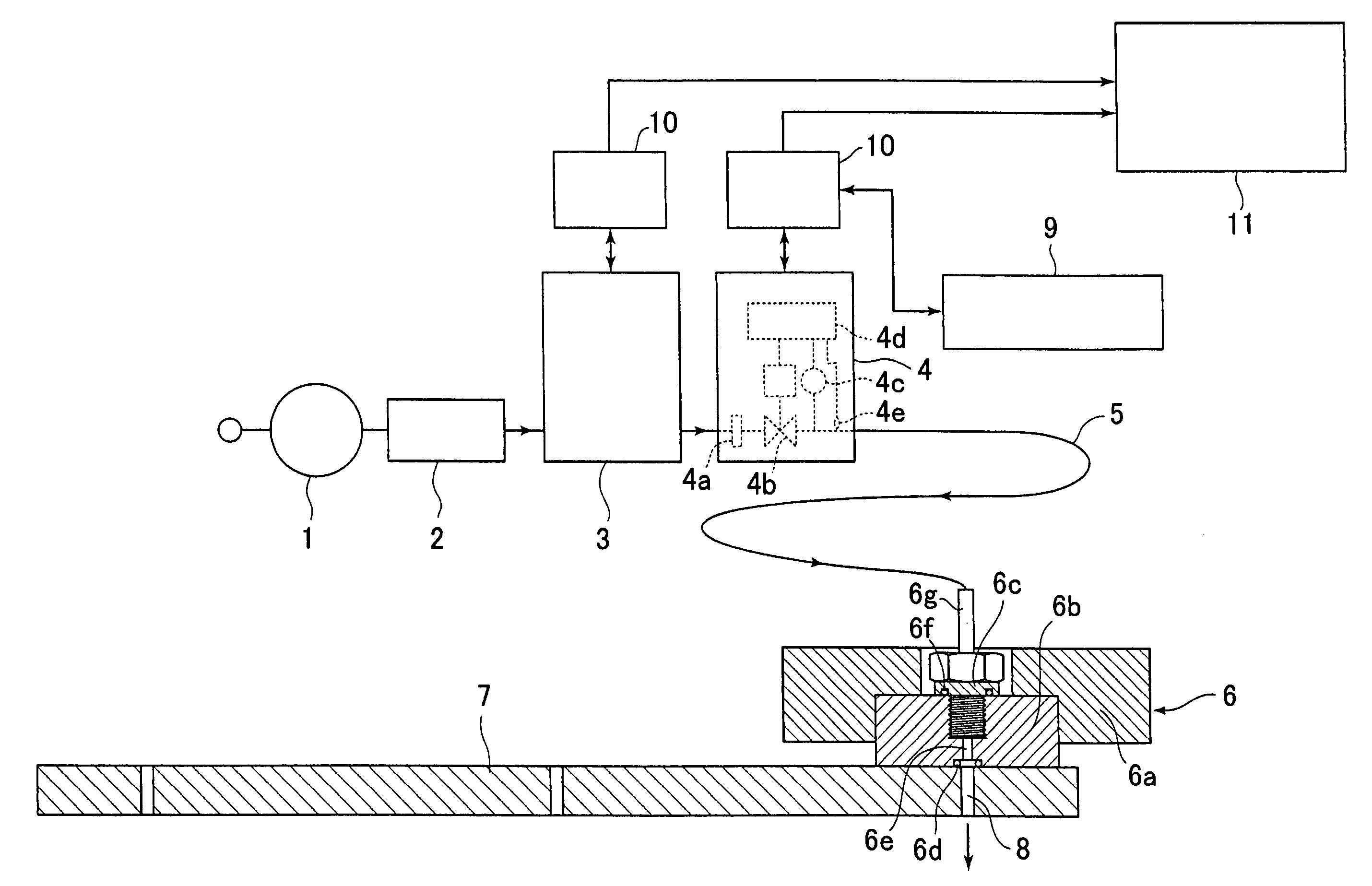
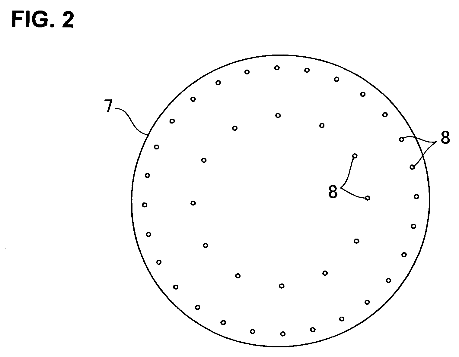
[0067]FIG. 1 is an outline diagram of a test apparatus used to obtain basic data for the present invention; and in this figure, the reference numeral 1 indicates a pressure adjustment device, 2 indicates a filter, 3 indicates a thermal quantity type mass flow controller (rating: 500 SCCM), 4 indicates an automatic pressure control device, 5 indicates a connecting tube (PFA tube, 3.2 mm φ×3 m), 6 indicates a test probe, 7 indicates a plate, 8 indicates small holes in the plate, 9 indicates an operating control panel, 10 indicates a power supply device, and 11 indicates a pen recorder.

[0068]The above-described automatic pressure control device 4 is comprised of a filter 4a, a control valve 4b, a pressure detector 4c, a calculation...


PUM

PropertyMeasurementUnit
diameteraaaaaaaaaa
thicknessaaaaaaaaaa
internal diameteraaaaaaaaaa

Abstract

A small hole diameter measuring apparatus including: a flow rate measurement section comprised of an automatic pressure control device which supplies a fluid to the inlet side of small holes in a plate while maintaining the outlet- and inlet-side pressures of the small holes in the critical state of the fluid and controlling the inlet-side pressure to a predetermined inlet-side pressure; a plate holding section comprised of a plate supporting device which rotatably holds the plate, and a test probe supporting device which supports a test probe so that the test probe is moved vertically and horizontally; and a control section comprised of a calculation and judgment part, which calculates the hole diameter during the supply of the fluid based upon the measured value of the flow rate from the flow rate measurement section, and an external output part, which outputs the calculated value to the outside.

Description

BACKGROUND OF THE INVENTION[0001]1. Technical Field[0002]The present invention relates to the measurement of the diameters of small holes formed in a substrate and more specifically relates to an improved system for the automatic measurement of the diameters of small holes formed in a plate such as the orifice diameter of a shower plate used for the disperse supply of a fluid (gas) in, for example, the vacuum chamber of a semiconductor manufacturing apparatus or the like. More concretely, the present invention relates to a small hole diameter measurement system for a plate in which the effective internal diameters of a plurality of small holes formed in a single plate can be automatically measured quickly and with high precision.[0003]2. Description of the Related Art[0004]In semiconductor manufacturing equipment and liquid crystal displays, due to an increase in the size of the materials that are treated, it is necessary to maintain in-plane uniformity. Accordingly, for example, in...

Claims


Application Information

Patent Timeline
Patent Type & Authority Patents(United States)
IPC IPC(8): G01M3/02G01B13/10
CPCG01B13/10Y10T29/49432B29C2793/0045B29L2023/18
Inventor OHMI, TADAHIRONAGASE, MASAAKIDOHI, RYOUSUKENISHINO, KOUJINAKAMURA, OSAMUUNO, TOMIOIKEDA, NOBUKAZU
Owner FUJIKIN INC
Why Eureka
Try Eureka