
System and method for feature compensation of an ablated inkjet nozzle plate

a technology of feature compensation and ablation inkjet, which is applied in the field of system and method of feature compensation of ablated inkjet nozzle plate, can solve the problems of difficult for very small regions, inconsistency of energy output throughout the entire width and length of laser beam, and adverse effects on printing quality

Inactive Publication Date: 2000-06-27
FUNAI ELECTRIC CO LTD
View PDF35 Cites 7 Cited by
  • Summary
  • Abstract
  • Description
  • Claims
  • Application Information

AI Technical Summary

Benefits of technology

As provided in step S130 of FIG. 4, a determination is made regarding the adjustment of the feature sizes of interest based on the measured features recorded in step S120 of FIG. 4. This is accomplished by determining the variance or difference between the measured features dimensions and a desired features dimensions. However, first it is necessary to eliminate random variations (noise) in the data for each nozzle number measured. This may be accomplished by using one or more of several mathematical and statistical algorithms including: averaging; linear modeling; nth order polynomials; quadratic modeling; and nonlinear modeling. A quadratic modeling method would include such techniques as a second order least squares curve fitting. In the preferred embodiment, quadratic modeling is preferred due to superior ability to eliminate outliers and its usefulness in interpolating between measured points. However, the quadratic modeling method has the disadvantage of requiring substantially more test parts ablated and significantly more measurements taken.
Once the curves representing segments of the measured nozzle holes is determined, these algebraic equations are used to determine the adjustment to the measured features (nozzle diameters) for the given segment. For example, if the goal is for all nozzle diameters to be 16.5 microns, the algebraic equation for the segment representing nozzle numbers 0-40 would reduce nozzle number 1, and nozzle numbers close thereto, by approximately 0.5 microns. Since, the reduction lens 70 reduces the coherent light beam emitted from mask 60 by a factor of five, the diameter of the mask holes in the vicinity of nozzle number 1 in mask 60 would be reduced by 2.5 microns to achieve the desired result.
The resulting measurements for the nozzle diameters versus nozzle number are graphed as shown in FIG. 3. It should be noted in FIG. 3, that the difference between nozzle diameters is significantly reduced.

Problems solved by technology

However, due to anomalies in the manufacturing of lens and the optical delivery system used in the laser system, the energy output is not consistent throughout the entire width and length of the laser beam.
Thus, the quality of printing would be adversely effected due to the variation in the feature size.
One such method of measuring the energy output of the laser system would simply employ a standard commercially available laser power meter, although this can be difficult for very small regions.

Method used


Image

  • System and method for feature compensation of an ablated inkjet nozzle plate
  • System and method for feature compensation of an ablated inkjet nozzle plate
  • System and method for feature compensation of an ablated inkjet nozzle plate

Examples


Embodiment Construction

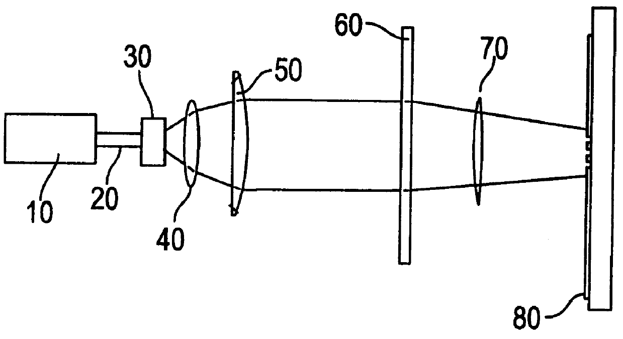
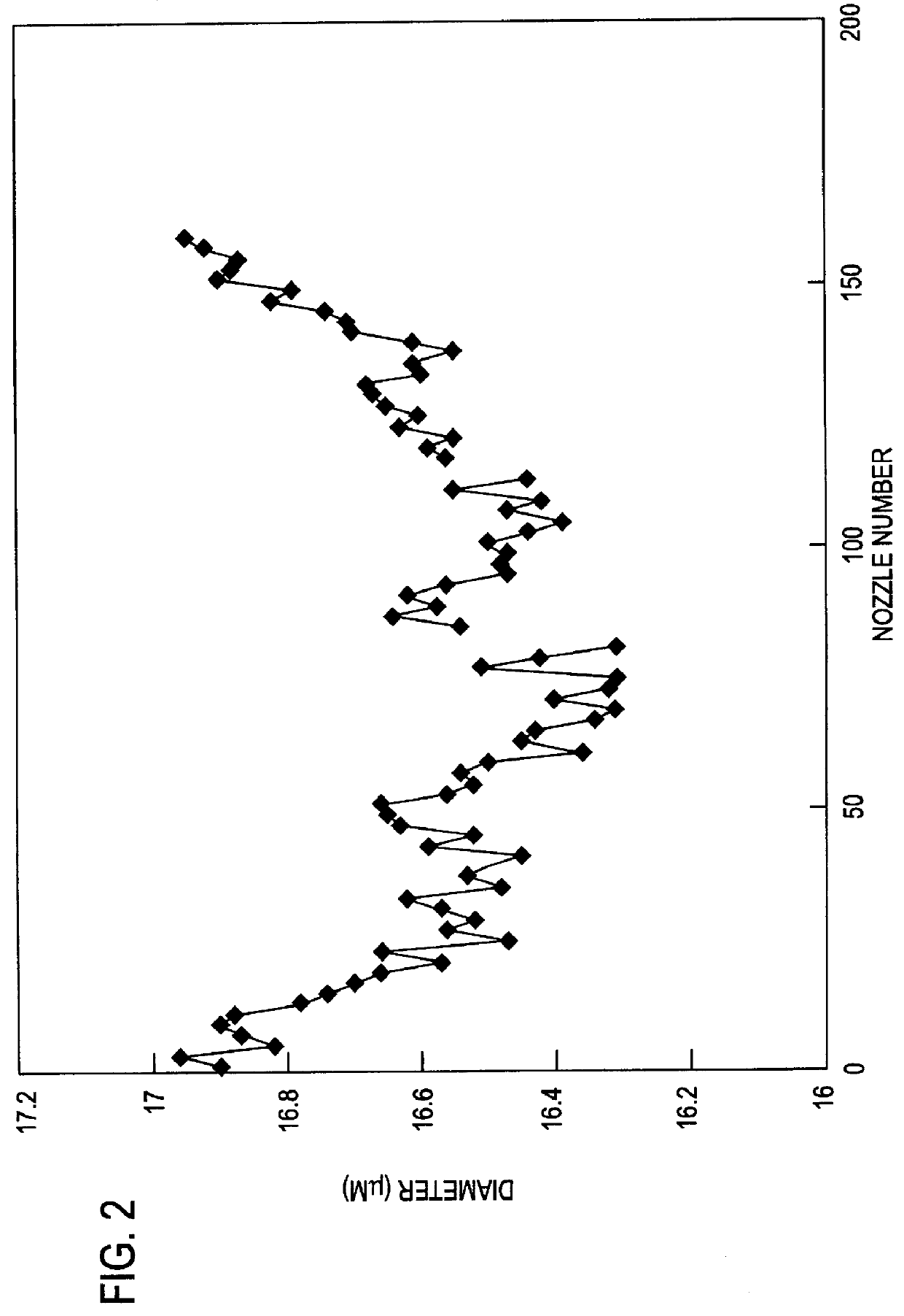
FIG. 4 is a flowchart of the method employed according to an embodiment of the present invention to create a mask 60 that compensates for the variations in nozzle diameter seen in FIG. 2 and FIG. 6B.

As provided in step S100 of FIG. 4, the laser system is setup to ablate the nozzle plate 80 under the assumption that no adjustment is necessary to the mask 60 in order to compensate for variations in the power output of the laser system. This setup procedure includes determining the laser 10 power settings and repetition rate necessary to ablate the desired amount of material from the nozzle plate 80.

As provided in step S110 of FIG. 4, the nozzle plate 80 is then ablated using the power settings and repetition rate determined in step S100. The mask 60 used is a standard mask with no compensation in feature sizes for variations in power output. However, a mask 60 in which selected features have been compensated for may also be used. Several nozzle plates 80 or test parts are ablated in a...


PUM

PropertyMeasurementUnit
Diameteraaaaaaaaaa
Dimensionaaaaaaaaaa
Energyaaaaaaaaaa

Abstract

A system and method of adjusting mask feature dimensions to compensate for anomalies in energy output of a laser beam used in ablating a workpiece. This method involves measuring the effects of variations in energy output of the laser beam at several points in the laser beam profile. In the case where the workpiece is a nozzle plate, the features adjusted in the mask are the diameters of the mask holes. Differences in the effects of the energy output between the points in the laser beam are then compensated for by adjusting the mask features that correspond to the points in the laser beam.

Description

1. Field of the InventionThe present invention relates to a system and method of compensating for variations in energy output of a laser. More particularly, the present invention relates to a system and method for adjusting mask dimensions to compensate for variations in energy output in an excimer laser used in ablating an inkjet nozzle plate.2. Description of the Related ArtExcimer lasers are widely used in industry to form minuscule structures in objects due to their high-energy output and precision. Frequently, a mask is employed in the laser ablation process so that the laser may ablate very complex structures. Excimer lasers have also found a place in the manufacture of inkjet nozzle plates. When manufacturing a nozzle plate for an inkjet printer it is necessary to form precise nozzle holes, firing chambers and channels. The quality of the ultimate printing is directly effected by the precision of the ablating of the nozzle plate by the excimer laser.In recent years users of c...

Claims


Application Information

Patent Timeline
IPC IPC(8): B23K26/06B23K26/38B23K26/00B41J2/16B41J2/135B23K101/36
CPCB23K26/0656B23K26/381B23K26/4065B41J2/162B41J2/1634B23K26/388B23K26/382B23K26/066B23K26/389B23K2103/42B23K2103/50
Inventor KOMPLIN, STEVEN ROBERT
Owner FUNAI ELECTRIC CO LTD
Learn More