Display apparatus

a display panel and display technology, applied in the field of display panels, can solve the problems of reducing affecting the display, and wasting energy to increase the brightness of the display, so as to reduce the influence of the transmittance of the display panel

Inactive Publication Date: 2015-09-17
INNOLUX CORP
View PDF13 Cites 0 Cited by
  • Summary
  • Abstract
  • Description
  • Claims
  • Application Information

AI Technical Summary

Benefits of technology

[0011]The object of the present invention is to provide a display apparatus comprising a reflecting film, which provides the mirror reflection function. The reflecting film reduces the influence of the transmittance of the display panel, and provides the need of mirror reflecting effect at the same time.

Problems solved by technology

However, it is energy-consuming to increase the brightness of the display.
In addition, the shielding effect of the metal thin film may fail the electrical function (such as touch function) of components under the metal thin film.
Therefore, the use of the metal reflecting film fails to provide an excellent mirror display apparatus with multi-functions.

Method used


Image

  • Display apparatus
  • Display apparatus
  • Display apparatus

Examples


embodiment 1

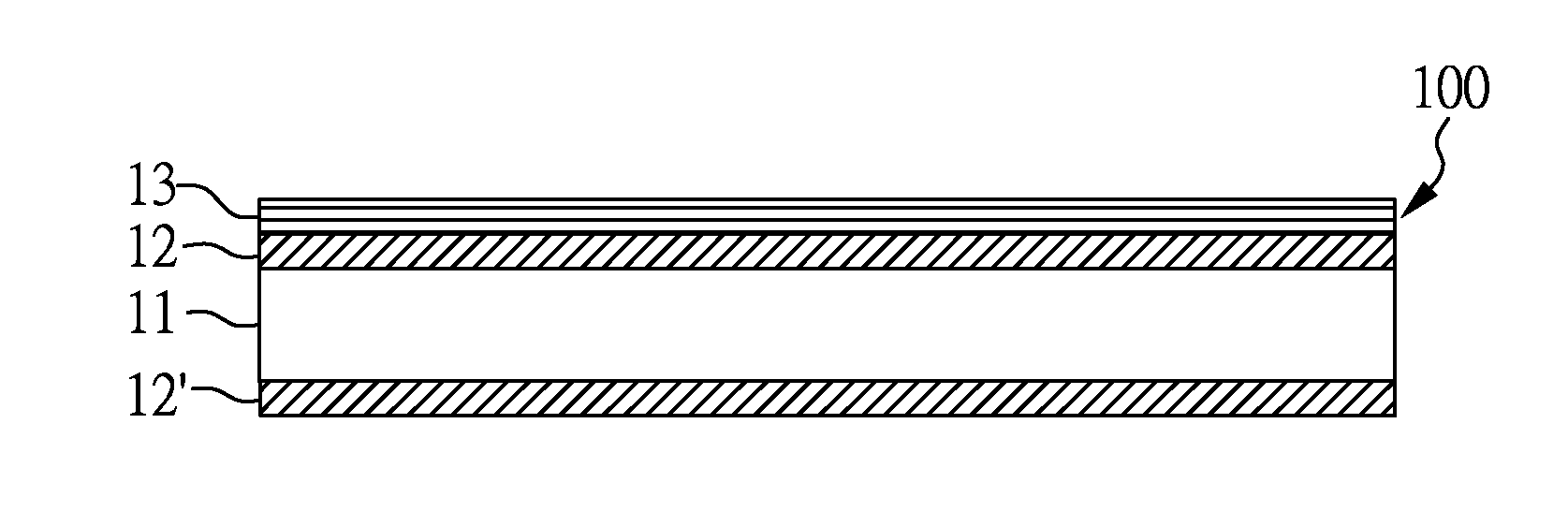
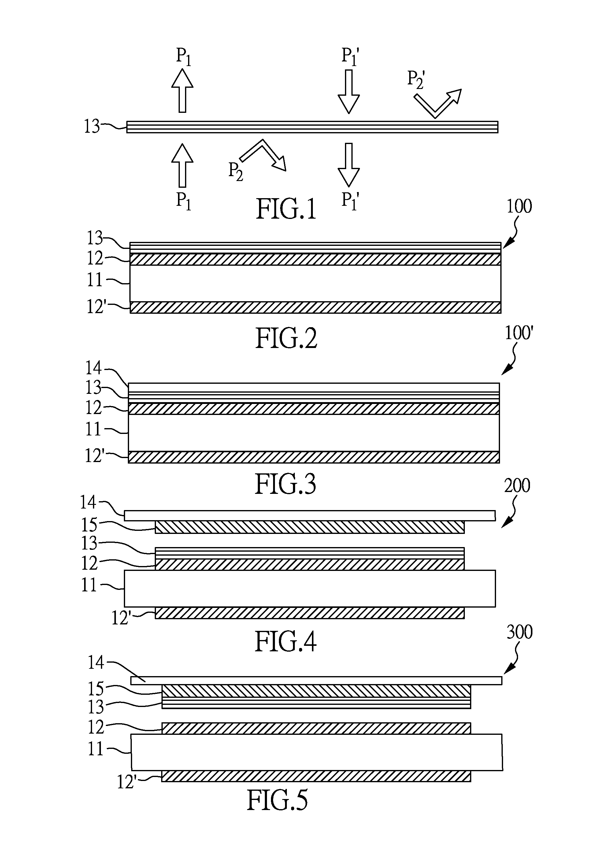
[0038]With reference to FIG. 2, there is shown a mirror display apparatus 100 of the present invention, the mirror display apparatus 100 comprises: a display panel 11, a first polarizing plate 12 disposing on the display panel 11, a second polarizing plate 12′ disposing under the display panel 11, and a reflecting film 13 disposing on the first polarizing plate 12. In the present embodiment, the reflecting film 13 has a first transmission axes, when a light with a polarization direction parallel to the first transmission axes of the reflecting film 13 irradiates onto the reflecting film, the light may penetrates into the reflecting film 13. However, if the polarization direction of the light irradiating onto the reflecting film is different from the first transmission axes of the reflecting film, portions of the light may be reflected by the reflecting film 13, and portions of the light may still penetrates through the reflecting film 13. In an embodiment, the first polarizing plate...

embodiment 2

[0044]FIG. 4 shows the touch mirror display apparatus 200 of the present embodiment, wherein the touch mirror display apparatus 200 comprises a display panel 11, a first polarizing plate 12 disposed on the display panel 11, a second polarizing plate 12′ disposed under the display panel 11, a reflecting film 13 disposed on the first polarizing plate 12, a touch element 15 disposed above the reflecting film, and a protective film 14 disposed on the touch element 15. The display panel 11, the first polarizing plate 12, the second polarizing plate 12′, the reflecting film 13, and the protective film 14 are the same as described above. Therefore, any description in the above Embodiment is incorporated herein insofar as the same is applicable, and the same description need not be repeated.

[0045]The touch element 15 of the present invention may be any types of touch sensor known in the art, for example, the touch element may be composed by a mono-layer touch thin film or a bi-layer touch t...

embodiment 3

[0047]FIG. 5 shows the touch mirror display apparatus 300 of the present embodiment, wherein the touch mirror display apparatus 200 comprises a display panel 11, a first polarizing plate 12 disposed on the display panel 11, a second polarizing plate 12′ disposed under the display panel 11, a reflecting film 13 disposed above the first polarizing plate 12, a touch element 15 disposed on the reflecting film, and a protective film 14 disposed on the touch element 15. The display panel 11, the first polarizing plate 12, the second polarizing plate 12′, the reflecting film 13, and the protective film 14 are the same as described above. Therefore, any description in the above Embodiment is incorporated herein insofar as the same is applicable, and the same description need not be repeated.

[0048]Alternatively, in other embodiments, the touch element 15 and the protective film 14 can be replaced by a Window integrated sensor (WIS).

[0049]In the present embodiment, the reflecting film 13 is d...


PUM


Abstract

A display apparatus and a touch display apparatus are disclosed, particularly, a display panel with functions including displaying and mirror reflection is disclosed. The display apparatus comprises display panel, a reflecting film disposed above the display panel, wherein the reflecting film has a first penetrating axes, wherein a display light is emitted from the display panel in a light-emitting direction, when an ambient light irradiates onto the display panel in a direction that different from the light-emitting direction, the ambient light with a polarization direction that different from the first transmission axes is reflected by the reflecting film.

Description

CROSS REFERENCE TO RELATED APPLICATION[0001]This application claims the benefits of the Taiwan Patent Application Serial Number 103134863, filed on Oct. 7, 2014, the subject matter of which is incorporated herein by reference.[0002]This application claims the benefit of filing date of U.S. Provisional Application Ser. No. 61 / 951,587, entitled “Mirror Display Apparatus” filed Mar. 12, 2014 under 35 USC §119(e)(1).BACKGROUND OF THE INVENTION[0003]1. Field of the Invention[0004]The present disclosure relates to a display apparatus, more particular, to a mirror display apparatus having a display function and a reflection function simultaneously.[0005]2. Description of Related Art[0006]For the popularity of Digital video devices, the development of the display technology continues to expand its applications fields, and the development of the display technology gradually moving toward multi-function display devises to realize the intelligent living style so that all kinds of messages may ...

Claims


Application Information

Patent Timeline
Patent Type & Authority Applications(United States)
IPC IPC(8): G02B5/30G02B5/08
CPCG02B5/08G02B5/30A47G1/02G02F1/13338G02F1/133528
Inventor KUO, CHENG-HSIACHEN, WEN-KUENPAN, TAI-CHI
Owner INNOLUX CORP
Why Eureka
Try Eureka