
Increased network scalability by router aware switches

a router-aware, network-scalability technology, applied in the field of storage area networks, can solve the problems of reducing the practical limit of the size of the fabric, affecting the scalability of the network, so as to reduce the processing burden, and reduce the impact of the ingress and egress switch

Active Publication Date: 2017-08-29
AVAGO TECH INT SALES PTE LTD
View PDF31 Cites 0 Cited by
  • Summary
  • Abstract
  • Description
  • Claims
  • Application Information

AI Technical Summary

Benefits of technology

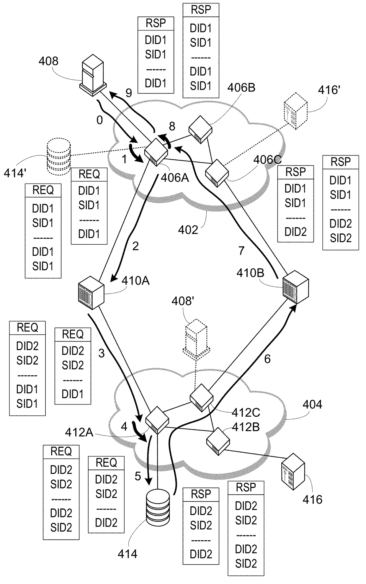
The present invention shifts the handling of ELS REQ and RSP packets with addresses in the payload to the edge fabric switches connected to the node devices issuing and receiving the ELS REQ packet, and the ingress and egress switches. This removes a processing burden from the router processors, allowing them to handle other normal operations. This growth of the network as one limitation has been removed. By moving the operations to the ingress and egress switches, there is no need to replicate or provide commands between switches or routers, and there is no consolidating factor of multiple flows from multiple node devices. This minimizes the impact on the ingress and egress switches as well.

Problems solved by technology

One architectural problem is a limited number of domains, commonly equated to switches.
However, other aspects of the protocol put a much lower practical limit on the size of a fabric.
The operations are so time and processor intensive that usually a fabric has many fewer domains for stability purposes.
This smaller practical domain limit and a practice of dedicating a domain to a switch results in a maximum fabric size much less than currently desired in modern large data centers.
While routers have allowed a large increase in overall network size, because of other Fibre Channel fundamental characteristics, even a router topology becomes a limiting factor in network size.
This is because each node device on a fabric can only use fabric local addresses but this would result in many address conflicts if the packet is just provided unchanged to another fabric.
For headers this translation can be setup to be performed almost entirely in switch ASIC hardware but payload address translation cannot be automated in a similar manner.
This slows down operations and may lead to a performance limitation, which then turns into a network size limitation.
When this multipath approach is applied to routers between fabrics, it complicates the handling of the ELS REQ and RSP packets.
These inter-router communications are all handled by the router processors, so they further exacerbate performance issues of the processors, as well as slow down operations due to wait times for router responses before the actual packets can be forwarded.
Therefore, while routers have allowed much larger networks to be developed practically, the networks are again at the limits of growth, in part due to limitations of router processors.

Method used


Image

  • Increased network scalability by router aware switches
  • Increased network scalability by router aware switches
  • Increased network scalability by router aware switches

Examples


Embodiment Construction

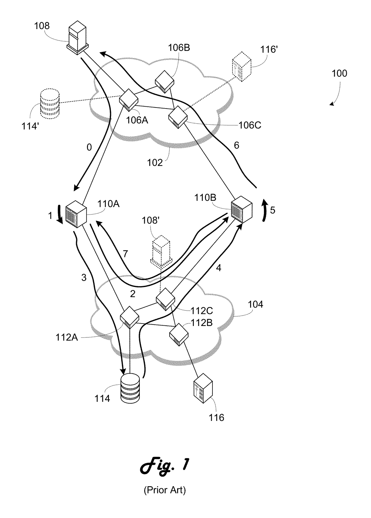
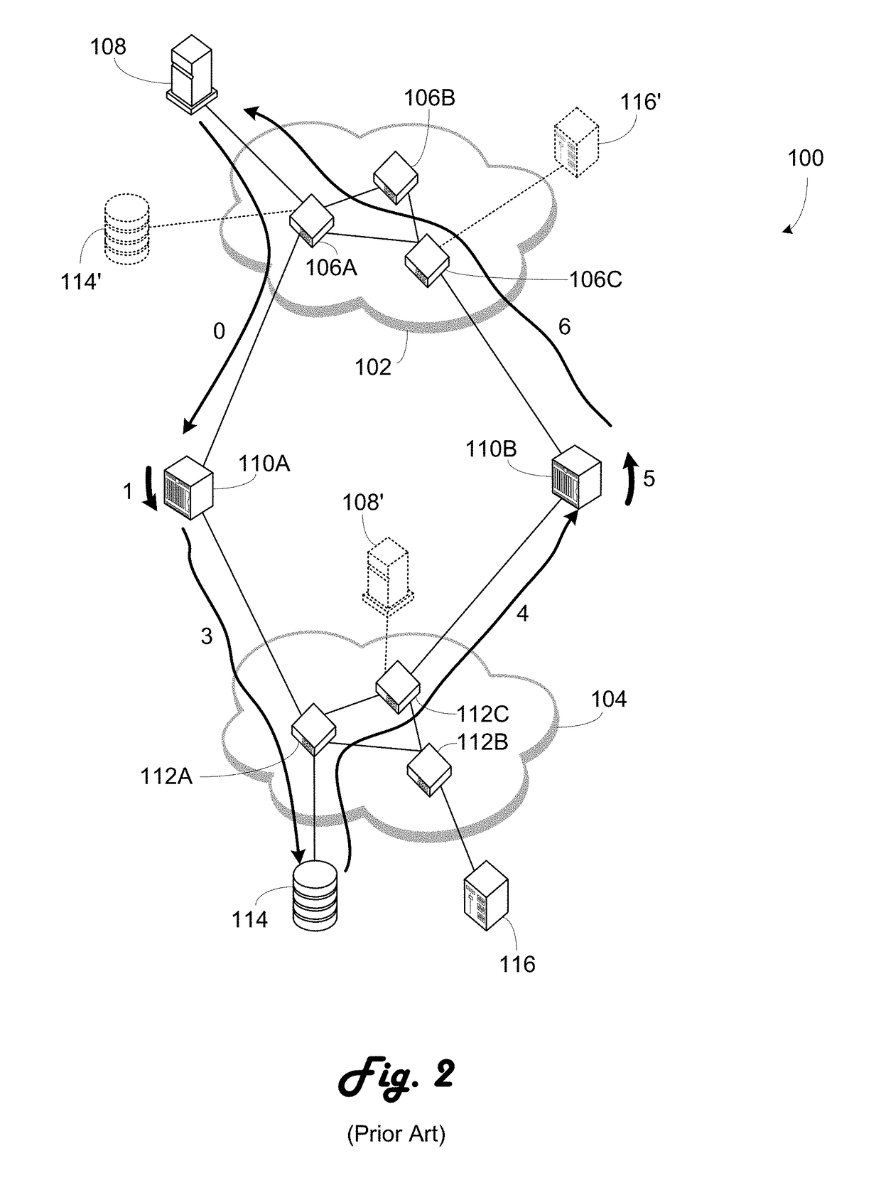
[0017]Referring now to FIG. 1, a network 100 illustrating flows according to the prior art is shown. Network 100 includes a first fabric 102 and a second fabric 104. The second first fabric 102 is formed by three switches 106A, 106B and 106C. A host or server node device 108 is connected to switch 106A. Fabric 104 is formed by three switches 112A, 112B and 112C. A disk storage unit 114 is connected to switch 112A while a tape storage unit 116 is connected to switch 112B. Switch 106A is also connected to a first router 110A. Router 110A is also connected to switch 112A. Switch 112C is connected to a second router 110B which is also connected to switch 106C.

[0018]By the operation of the routers 110A and 110B phantom devices appear in fabrics 102 and 104. Disk storage unit 114′ appears to be connected to phantom domain created by the router 110A, the phantom domain appearing as part of the first fabric 102. To simplify FIG. 2, the disk storage unit 1114′ is shown connected to switch 10...


PUM


Abstract

Handling of ELS REQ and RSP packets that contain addresses in the payload is shifted to the edge fabric switches connected to the node devices issuing and receiving the ELS REQ packet, the ingress and egress switches. This allows the ELS REQ and RSP packet payload address modification operations to be removed from the tasks handled by the router processor. As this removes a processing burden from the router processors, those router processors are free to handle other normal operations, thus allowing more processor bandwidth to be provided to those other operations, which allows further growth of the network as one limitation has been removed. The need to replicate or provide commands between switches or routers is avoided as there are no redundant paths at that point.

Description

BACKGROUND OF THE INVENTION[0001]1. Field of the Invention[0002]The present invention relates generally to storage area networks.[0003]2. Description of the Related Art[0004]Fibre Channel has been a preferred protocol for data center storage for many years and continues to be so. This is true despite some architectural problems with Fibre Channel. One architectural problem is a limited number of domains, commonly equated to switches. For one fabric Fibre Channel has a theoretical maximum of 239 domains, each capable of theoretically 256 areas, each with a theoretical limit of 255 devices. However, other aspects of the protocol put a much lower practical limit on the size of a fabric. One such aspect relates to operations that must occur when a switch is added to or removed from the fabric. The operations are so time and processor intensive that usually a fabric has many fewer domains for stability purposes.[0005]This smaller practical domain limit and a practice of dedicating a doma...

Claims


Application Information

Patent Timeline
Patent Type & Authority Patents(United States)
IPC IPC(8): H04L12/28H04L12/741H04L45/74
CPCH04L45/74
Inventor KOLLU, BADRINATH
Owner AVAGO TECH INT SALES PTE LTD
Learn More