Antenna device for RFID reader/writer

Active Publication Date: 2015-09-17
NORDIC ID
View PDF4 Cites 6 Cited by
  • Summary
  • Abstract
  • Description
  • Claims
  • Application Information

AI Technical Summary

Benefits of technology

The invention is about improving the connection between an RFID reader / writer and an RFID tag by using a special antenna system. The antenna system can radiate both linear and circular polarized radio waves, which allows for more effective reading and writing of the RFID tag, regardless of its orientation. This also allows for the use of smaller antenna structures in the RFID tags, which helps ensure reliable reading and writing. Overall, the invention provides better performance and flexibility in RFID systems.

Problems solved by technology

However, using the same antenna in different circumstances does not provide the best read rates or the required read zone.
Any reflection, diffraction or absorption changes the read zone and anything that propagates a wave can cause signal strength degradation.
Exact orientation of the tag antenna is not easy to control.
This is problematic especially if the linearly polarized antenna of the reader / writer is orthogonal to the linearly polarized antenna of the tag because there is no electric field along the direction of the propagation axis.
This means that no voltage will transfer from the reader / writer to power the microchips of the tag and that communication between the two will be impossible.
However, the use of omnidirectional antennas in tags is critical because their size.

Method used


Image

  • Antenna device for RFID reader/writer
  • Antenna device for RFID reader/writer
  • Antenna device for RFID reader/writer

Examples


Embodiment Construction

[0029]When an electromagnetic wave is radiated electrons move in the plane perpendicular to the direction of propagation of the wave. The direction in which the electric field points, determines the polarization of the radiated wave. When this direction is constant in time, the wave is linearly polarized. Linearly polarized antennas are typically oriented either vertically or horizontally. Also any intermediate angle is possible because the electric field can point in any direction in the plane perpendicular to the direction of propagation.

[0030]However, the direction in which the electric field points, i.e. the direction of polarization, is often time dependent. When the electric field rotates around the axis of propagation as a function of time, without changing its magnitude, circularly polarized wave is produced. Depending on the sense of rotation circular polarization is said to be either right-handed or left-handed. Circular polarized radiation can be regarded as the sum of ve...


PUM


Abstract

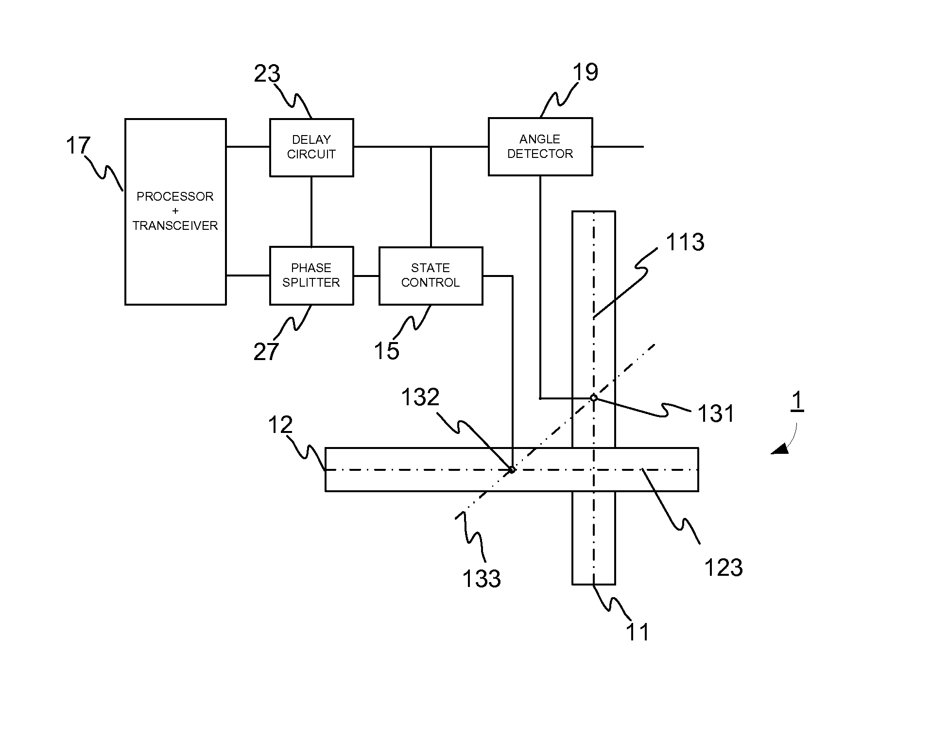
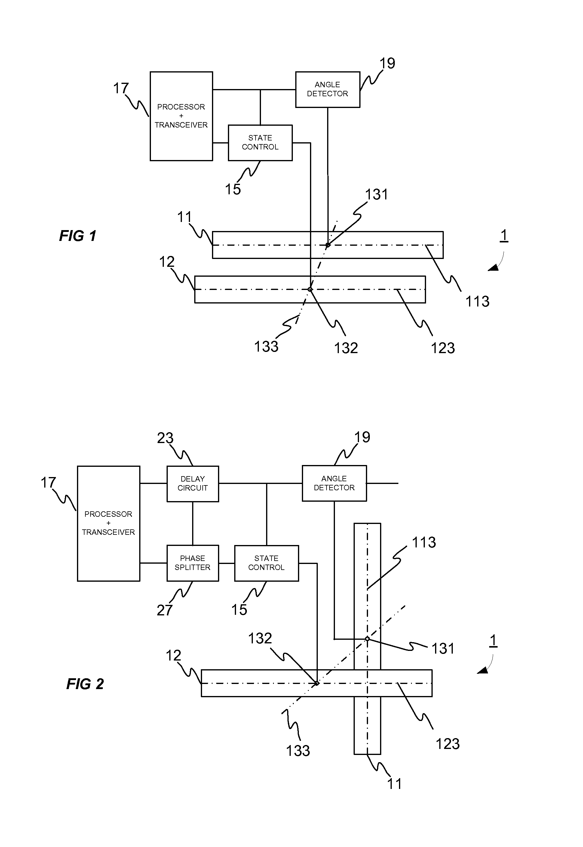
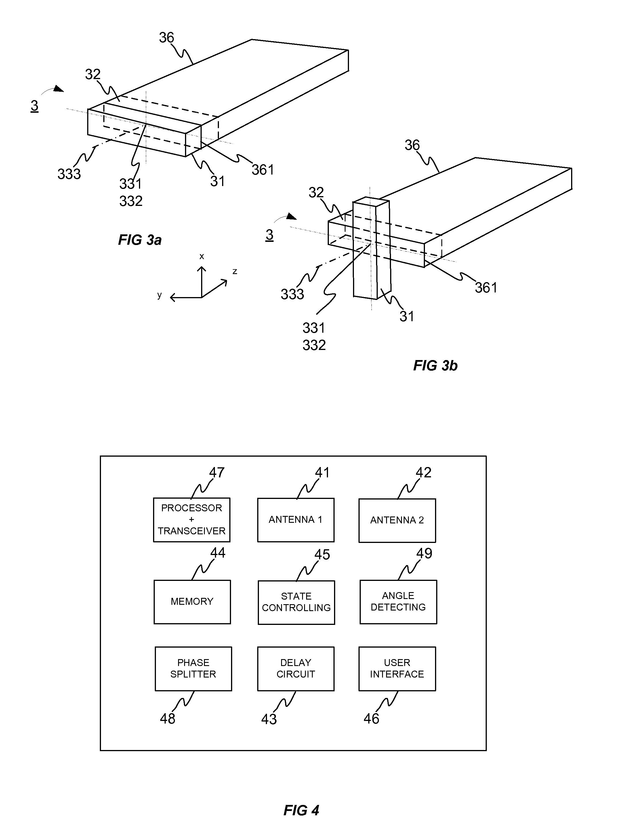
An antenna device that includes a pair of antenna elements for an RFID reader / writer to communicate information with an RFID tag is provided. The antenna elements are movably connected to each other so that one of the antenna elements is configured to intensify the other of the antenna elements to radiate radio wave. The antenna device has at least operation modes, where the antenna elements are in parallel to each other and where the antenna elements are orthogonal to each other. The RFID reader / writer device includes such a pair of antenna elements.

Description

TECHNICAL FIELD[0001]The invention relates to RFID (Radio Frequency Identification) reading or writing devices and more particular an antenna device that improves operation of the RFID reading or writing device.BACKGROUND[0002]In an RFID system a reader / writer needs a transmitting antenna to convert a voltage created by the reader / writer to an electromagnetic wave that is transmitted as a radio signal to a tag being attached to an object. The reader / writer also needs a receiving antenna to detect a radio signal received from the tag. These two antennas are realized by a pair of antennas being physically separated in close proximity to each other or a single antenna that is used for both transmitting and receiving signals.[0003]However, using the same antenna in different circumstances does not provide the best read rates or the required read zone. Any reflection, diffraction or absorption changes the read zone and anything that propagates a wave can cause signal strength degradation...

Claims


Application Information

Patent Timeline
IPC IPC(8): G06K7/10H01Q1/22
CPCG06K7/10178H01Q1/2216G06K7/10356H01Q21/24H04B7/10H01Q3/02H01Q9/16H04B5/77G06K7/015G06K7/10198G06K19/067H01Q1/1264H01Q3/01H01Q3/12H01Q19/22
Inventor RUOTSALAINEN, SAMI
Owner NORDIC ID
Why Eureka
Try Eureka