Integrated optical and charged particle inspection apparatus

a technology of integrated inspection and charged particles, which is applied in the direction of material analysis using wave/particle radiation, instruments, nuclear engineering, etc., can solve the problems of cumbersome process, non-trivial process of achieving the overlay, and different magnification of both images, so as to improve the quality and accuracy of inspection, reduce the complexity of correlative inspection, and improve productivity

Active Publication Date: 2015-09-17
DELMIC IP BV
View PDF1 Cites 15 Cited by
  • Summary
  • Abstract
  • Description
  • Claims
  • Application Information

AI Technical Summary

Benefits of technology

[0011]In the present invention a fundamental improvement is made in the practice of correlative microscopy, by an at hindsight relatively simple measure that obviates the specific manners for doing so as known to date. The measure according to the invention r...

Problems solved by technology

The problem in this practice is that both images have different magnification, possibly both in x and y, and a rotated orientation.
Also, the images have different contrast, ...

Method used


Image

  • Integrated optical and charged particle inspection apparatus
  • Integrated optical and charged particle inspection apparatus
  • Integrated optical and charged particle inspection apparatus

Examples


Embodiment Construction

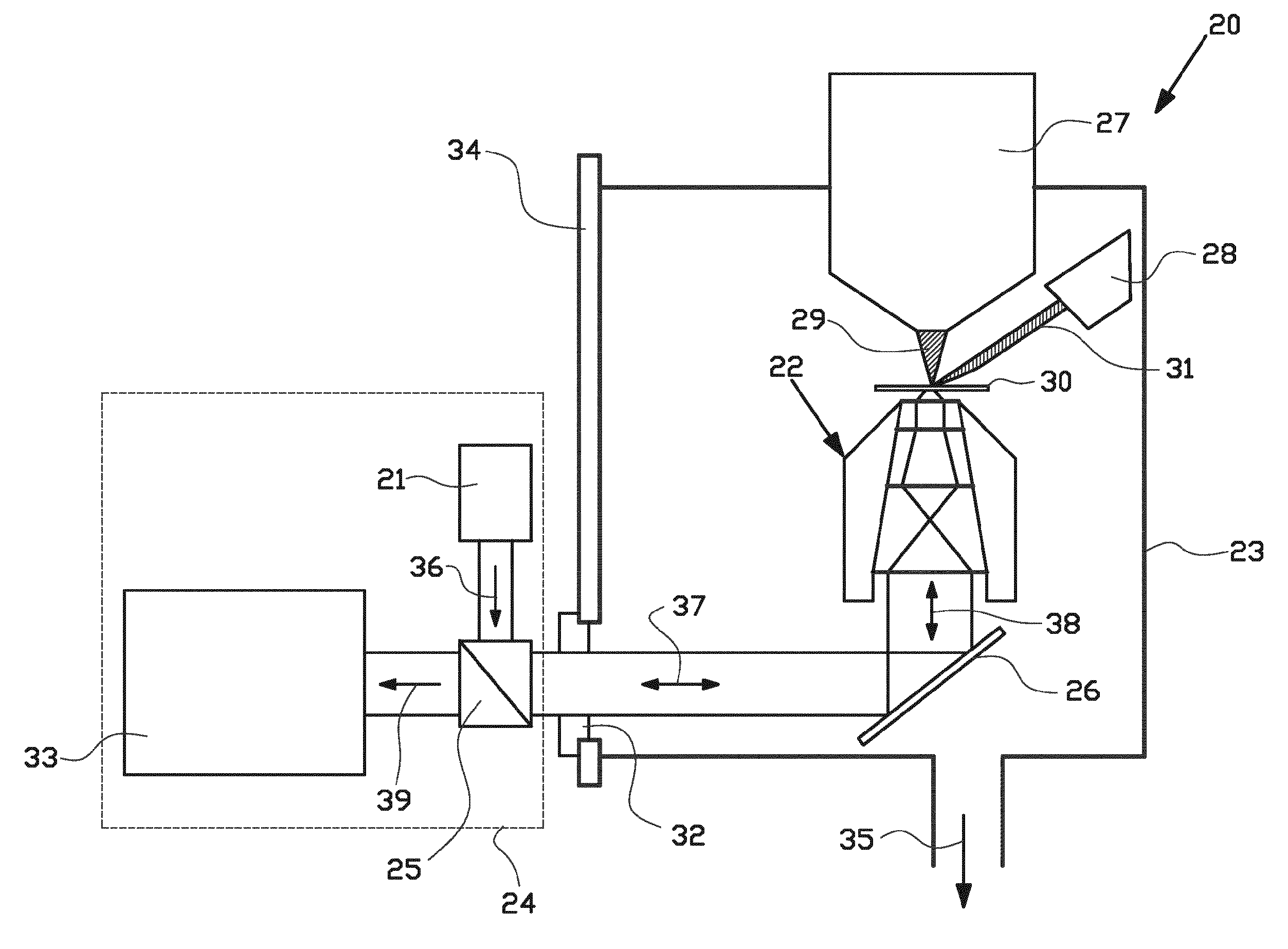
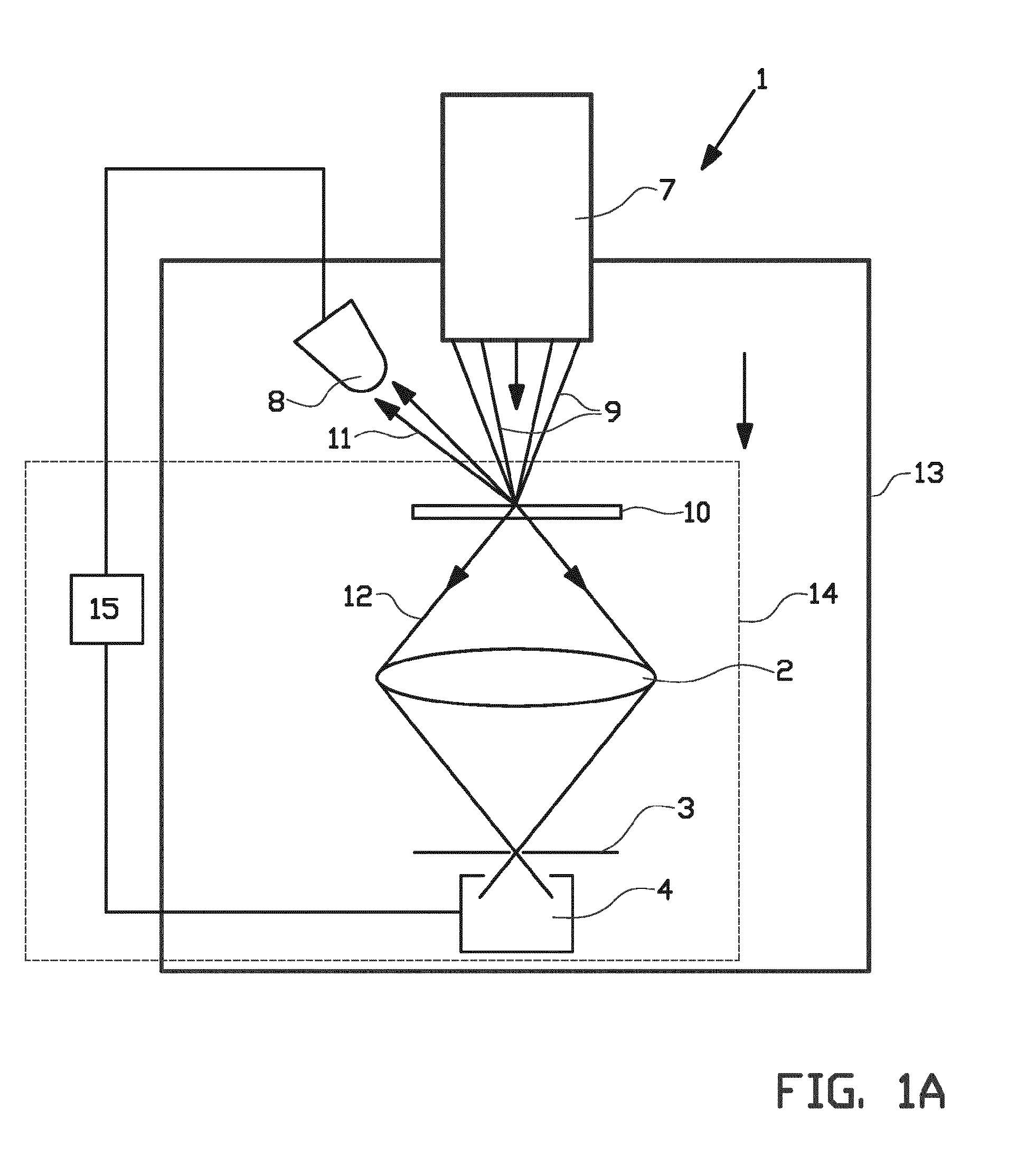
[0056]By way of exemplifying a typical context of the present invention, a principle and relatively simple set up of a so-called optical SEM combination as known from the prior art will be provided. This example however by no means excludes any known or yet unknown variation or alternative thereof. Hence, with reference first to FIG. 1, the basic design of a first example of an inspection apparatus 1 of the invention is explained. It comprises in combination at least an optical microscope 2, 3, 4 and a charged particle microscope 7, 8, such as an ion- or electron microscope.

[0057]The charged particle microscope 7, 8 comprises a source 7 for emitting a primary beam 9 of charged particles to a sample 10 supported by a substrate included in a sample holder. The apparatus comprises a detector 8 for detection of secondary charged particles 11 backscattered from the sample 10, or emitted, transmitted, or scattered from the sample 10 and possibly induced by the primary beam 9. The charged ...


PUM


Abstract

The present invention relates to a method for mutually aligning a scanning electron microscope SEM and a light microscope LM by creating a change (61) in the detected light signal of the light microscope LM by illuminating a substrate with an electron beam, correlating the position of the electron beam in the coordinate system of the scanning electron microscope SEM to the position of the observed change in the detected light signal in the coordinate system of the light microscope LM, and relatively shifting the scanning electron microscope SEM and the light microscope LM with respect to one another to a desired relative position of the coordinate systems (60, 62).

Description

BACKGROUND OF THE INVENTION[0001]1. Field of the Invention[0002]The present invention relates to an improvement in a so-called integrated inspection apparatus, featuring the integration of a scanning electron microscope (SEM) and light microscope optics. The improvement in particular relates to extension in functionality of such integrated systems, amongst others towards a new and simplified method of operating such systems.[0003]In this respect, it is noted that information obtained from images with light microscopy and electron microscopy is to a large extent complementary. With a light microscope different objects can be seen and inspected in a specimen in different colors, which allows for identification of part or whole of the composition of this specimen. Instead of directly observing color from a constituent of the specimen, very often specific color markers are attached, such as fluorophores or autofluorescent proteins, to a specific non-colored constituent for identificatio...

Claims


Application Information

Patent Timeline
IPC IPC(8): H01J37/02H01J37/28H01J37/22
CPCH01J37/023H01J37/222H01J37/228H01J2237/2801H01J2237/221H01J2237/2482H01J37/28H01J2237/2808
Inventor HOOGENBOOM, JACOB PIETERZONNEVYLLE, AERNOUT CHRISTIAANKRUIT, PIETERNARVAEZ-GONZALEZ, ANGELA CAROLINA
Owner DELMIC IP BV
Why Eureka
Try Eureka