Customized Breathing Mask

a breathing mask and custom technology, applied in the field of custom breathing masks, can solve the problems of low fit factor of the mask, discomfort, pain or leakage of air, mask may not stay in place, etc., and achieve the effects of hygienic use, improved fit factor and cost saving

Inactive Publication Date: 2015-09-24
CPG MEDICAL
View PDF0 Cites 24 Cited by
  • Summary
  • Abstract
  • Description
  • Claims
  • Application Information

AI Technical Summary

Benefits of technology

[0020]It is an object of the invention to provide a cost efficient method for manufacturing a mask, preferably a Positive Airway Pressure mask which has an improved fit factor, is hygienic in use because of its construction, and provides an improved comfort in wearing and a saver use. Furthermore it is an object of the invention to provide a PAP mask, providing these objectives.
[0021]The invention realizes the objectives in the following manner. Firstly a subject's face is captured, using 3D capturing technology such as 3D cameras. The captured image is input for a rapid prototyping manufacturing process. The PAP mask is then manufactured in one production run (in a continuous process). With modern rapid prototyping technologies, and especially by applying additive manufacturing or 3D printing, it is possible to change types of material during the printing process. This provides the surprisingly effective possibility to integrate a seal into the edge of the mask, instead of manufacturing a separate cap and a separate seal, as currently is the state of the art technology. In this way the seal and the cap of the mask (the cap being the mask part without the seal), are seamlessly joined. This saves one assembly step, which in turn saves costs on the one hand, and prevents possible leakage because of a bad connection between the seal and the cap on the other hand.
[0023]Thus a very good fit factor is achieved, which leads to an increased comfort in wearing and at least as important, a saver use, because of considerable less possibility of air leakage. Moreover, because of the seamless integration of a seal, there is less chance of bacteria and dirt to collect in cavities, therefore a sanitary improvement is achieved.
[0024]In order to increase comfort and safety and to lower production costs, the 3D manufacturing process allows incorporating attachment means for supplementary devices, according to the needs or wishes of the subject, which increase either comfort or safety. One may think of a sensor which detects if a leakage occurs, despite of the good fit factor. The subject may for example turn in his sleep and the mask may get loose accidentally, without the subject noticing it. Such a sensor will be able to detect this leak and gives a warning signal.

Problems solved by technology

A major issue with PAP is non-compliance.
Prospective PAP candidates are often reluctant to use this therapy, since the mask feels uncomfortable and has other disadvantages.
These disadvantages of conventional masks are mainly caused by a too low Fit Factor (FF) of the mask, wherein a higher FF indicates better fit between the face and the mask and less leakage of air.
Second, conventional masks may not account for differences in the sizes, shapes (such as facial irregularities) of the facial features of different subjects, thus causing discomfort, pain or leakage of air.
Third, because of the poor seals or fits often associated with conventional masks, the mask may not stay in place, and may shift or move.
If the mask does not stay in place, or if the mask does not fit closely to the face, air may leak and the air pressure will drop, thereby nullifying the aimed effect of positive pressure.
This requires a fair amount of effort and time, and is therefore costly.
It also causes a lot of discomfort and for children and in particular newborns, this is almost impossible to do.
Although surface scanning of an individual subject leads to a quite accurate capturing of the subject's face surface, and although the captured image may lead to a better fit factor when using rapid prototyping technologies, the comfort for the subject in wearing the mask may often still be insufficient, or even worse than masks produced in an old fashioned manner using a plaster mould and a lot of craftsmanship.
This may feel uncomfortable for the subject when the mask is pressed tightly on the subject's face by fastening the mask around the subject's head with for example elastic straps.
The extra seal has the disadvantage that it results in a mask with more complexity, and an extra point of failure.
A further disadvantage is that every extra joint between parts of the mask is a possible area for accumulation of dirt and bacteria, which may cause sanitary problems.

Method used


Image

  • Customized Breathing Mask
  • Customized Breathing Mask
  • Customized Breathing Mask

Examples


first embodiment

[0044]In the invention, the capturing of one or more images comprises capturing of one or more images of at least a portion the face which is in a substantially horizontal upward facing position. By capturing the face while the subject is lying on his back, the face may assume a position which is favourable when the subject lies asleep. The face will deform such that soft facial tissue will be indented because of gravity. By consequence the shape of the mask will have an improved fit factor, especially in the situation wherein the subject is asleep, lying on his back. If the subject is upright however, the shape of the mask will be such that the contour of the edge will provide an extra force on the softer parts of the face. This will increase the fit factor even more, because of an improved distribution of force along the edge.

second embodiment

[0045]In a second embodiment, an additional step is performed before capturing of one or more images, the additional step comprising applying an indentation force on at least a portion of the face. Instead of or in addition to capturing the face in a horizontal position, the face may be deliberately and targeted impressed by a mechanical force. The indentation force may be provided in the simplest form by pushing fingers into the softer parts of the face, or by applying a spring load to specific parts of the face. Also a transparent object may be used to apply the force. In the computer processing of the captured images, it is possible to erase the devices or hand which has applied the indentation force if necessary. The advantage of having a captured indented face is that the mask can be printed such that it will exert more force on the softer parts of a relaxed face. In turn this will lead to a more even distribution of force of the mask on the face. Especially the less resilient ...

third embodiment

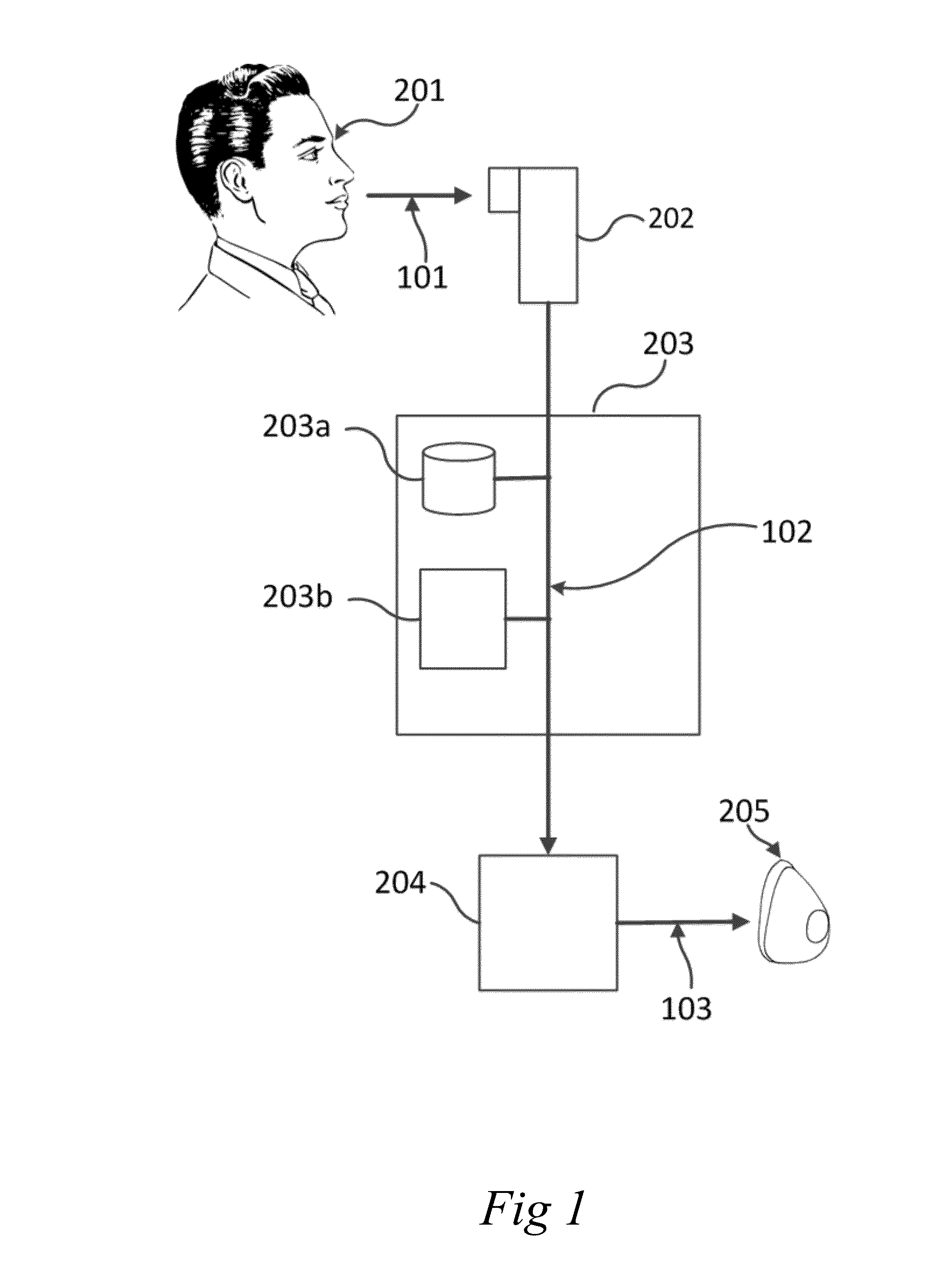
[0046]In a third embodiment, capturing of one or more images of the face of the subject comprises using an image capturing technique of the group comprising:

[0047]Photometric scanning, such as system using a single camera taking multiple images;[0048]laser scanning;[0049]stereo photography;[0050]tactile imaging.

[0051]These capturing techniques provide images which are accurate, quick and easy to make, and with minimum discomfort for a subject. By using these techniques, no plaster is needed anymore. Plaster is considered very uncomfortable, because of coverage of parts of the face and the relatively long duration of this multi-stage procedure. The images captured with these techniques are easy to use in computer aided manufacturing processes and in particular in rapid prototyping processes. Especially photometric scanning is effective because it requires no laser emitted at the subject, or touching of the subject. By moving the video camera around the subject, an accurate 3D image c...


PUM

PropertyMeasurementUnit
three-dimensional structureaaaaaaaaaa
resilientaaaaaaaaaa
indentation forceaaaaaaaaaa

Abstract

The present invention relates to a manufacturing method and a device for use in breathing assistance systems. The invention provides a cost efficient method for manufacturing a Positive Airway Pressure mask which has an improved fit factor and provides an improved comfort in wearing and a saver use. The mask is produced using 3D rapid prototyping technology using a 3D scan of a subject's face as input. A sealing edge is integrated in the one piece mask.

Description

CROSS-REFERENCE TO RELATED APPLICATIONS[0001]The present invention claims the benefits of priority from Netherlands patent application NL1039895, filed Nov. 13, 2012, the disclosure of which is incorporated herein by reference.TECHNICAL FIELD[0002]This invention relates generally to the field of breathing assistance systems, i.e. systems and methods for providing custom masks for use in a breathing assistance system.BACKGROUND OF THE INVENTION[0003]Currently, Positive Airway Pressure (PAP) is a mode of respiratory ventilation used primarily in the treatment of sleep apnea, for which it was first developed. PAP ventilation is also commonly used for those who are critically ill in hospital with respiratory failure, and in newborn infants (neonates). In these patients, PAP ventilation can prevent the need for tracheal intubation, or allow earlier extubation. Sometimes patients with neuromuscular diseases use this variety of ventilation as well. PAP is realized with a nose or face mask ...

Claims


Application Information

Patent Timeline
Patent Type & Authority Applications(United States)
IPC IPC(8): A61M16/06A61M16/00A61M11/06
CPCA61M16/0616A61M16/0683A61M11/065A61M16/0003B33Y80/00A61M2016/003A61M2205/3334A61M2205/3368B33Y10/00A61M2016/0027A61M16/06A61M2016/0661A61M2205/15A61M2016/0039A61M2016/103A61M2205/3375A61M2207/00A61M16/109A61M16/161B29C64/118B29C64/106
Inventor DE KRUYFF, CORNELISEIKELENBOOM, WILLEM PAUL EDUARDDE BRUIJN, GOVERT MACHIEL
Owner CPG MEDICAL
Why Eureka
Try Eureka