Catheter with Gills

a catheter and gill technology, applied in the field of catheters with gills, can solve the problems of catheters being more likely to block or limit blood flow, catheters may restrict or fully block the flow of blood, and inducing heart myocardial ischemia

Inactive Publication Date: 2015-09-24
VAKILI AHMAD D +1
View PDF6 Cites 9 Cited by
  • Summary
  • Abstract
  • Description
  • Claims
  • Application Information

AI Technical Summary

Problems solved by technology

In such cases, the catheter may restrict or fully block the flow of blood into the region fed by the artery into which it is inserted.
When blood flow is restricted or shut of to a region of the heart by a catheter for a while this may result in a catheter induced heart myocardial ischemia, which is not desirable.
The catheter is more likely to block or limit blood flow when used under certain situation such as in hard to reach narrow arteries.
This reduces the occurrence of situations where the lack of blood flow to regions supplied by the artery may lead to myocardial ischemia, which is induced by the catheter obstructing blood flow.
Unfortunately, these blood inlet holes also result in tracer dye leaving the catheter through the holes into the main blood stream, which affects the diagnostic accuracy of the procedure by reducing contrast, and, thus, is not desirable.
There are a few fundamentally undesirable disadvantages associated with wide use of the GCSH.
The first disadvantage is that the solid catheter must he removed and replaced with the GCSH.
This increases the time required for the operation and potentially increases complications due to the frequent removal and insertion of the different catheters.
The leaking of dye limits the contrast and resolution of the images and potentially the accuracy of diagnostics.
Unfortunately, this leads to injecting the patient with more dye than ideally would be required.
The increased dose of dye exposes the patient to greater risk of Nephrotoxicity.

Method used


Image

  • Catheter with Gills
  • Catheter with Gills
  • Catheter with Gills

Examples


Embodiment Construction

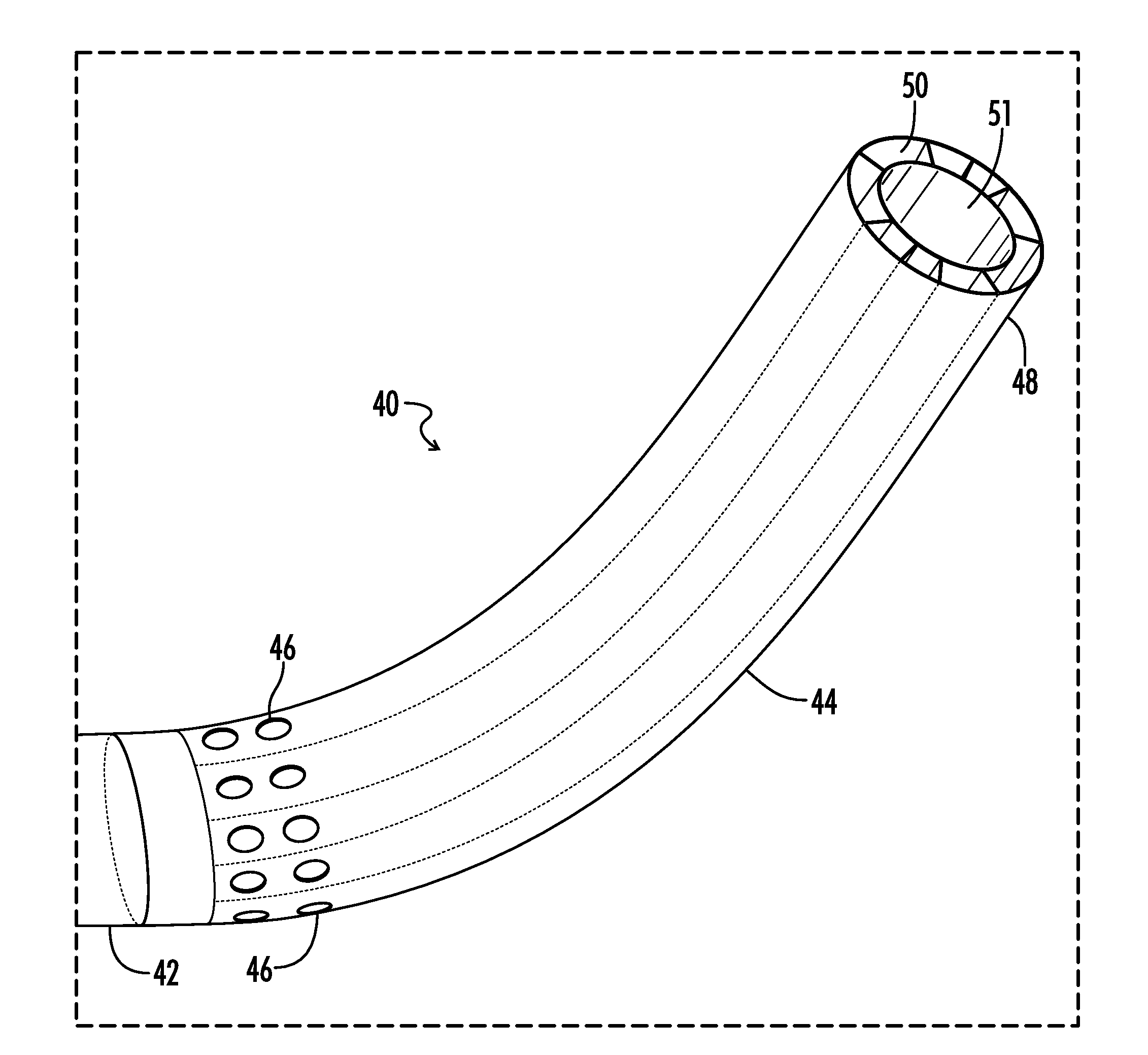
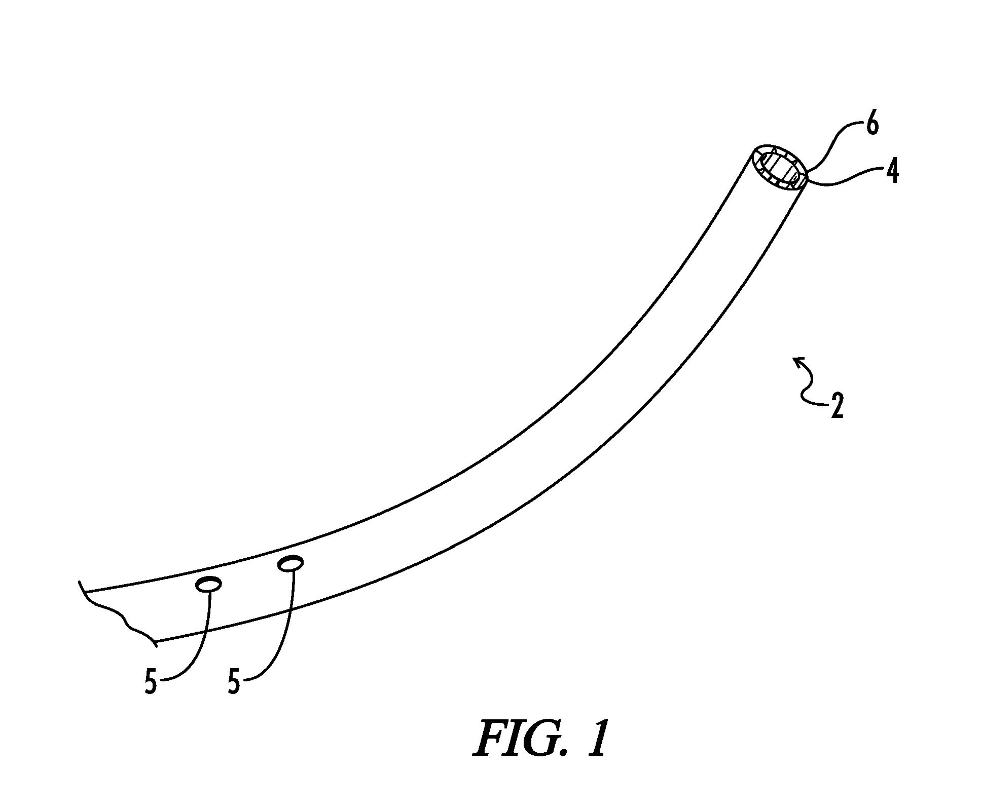
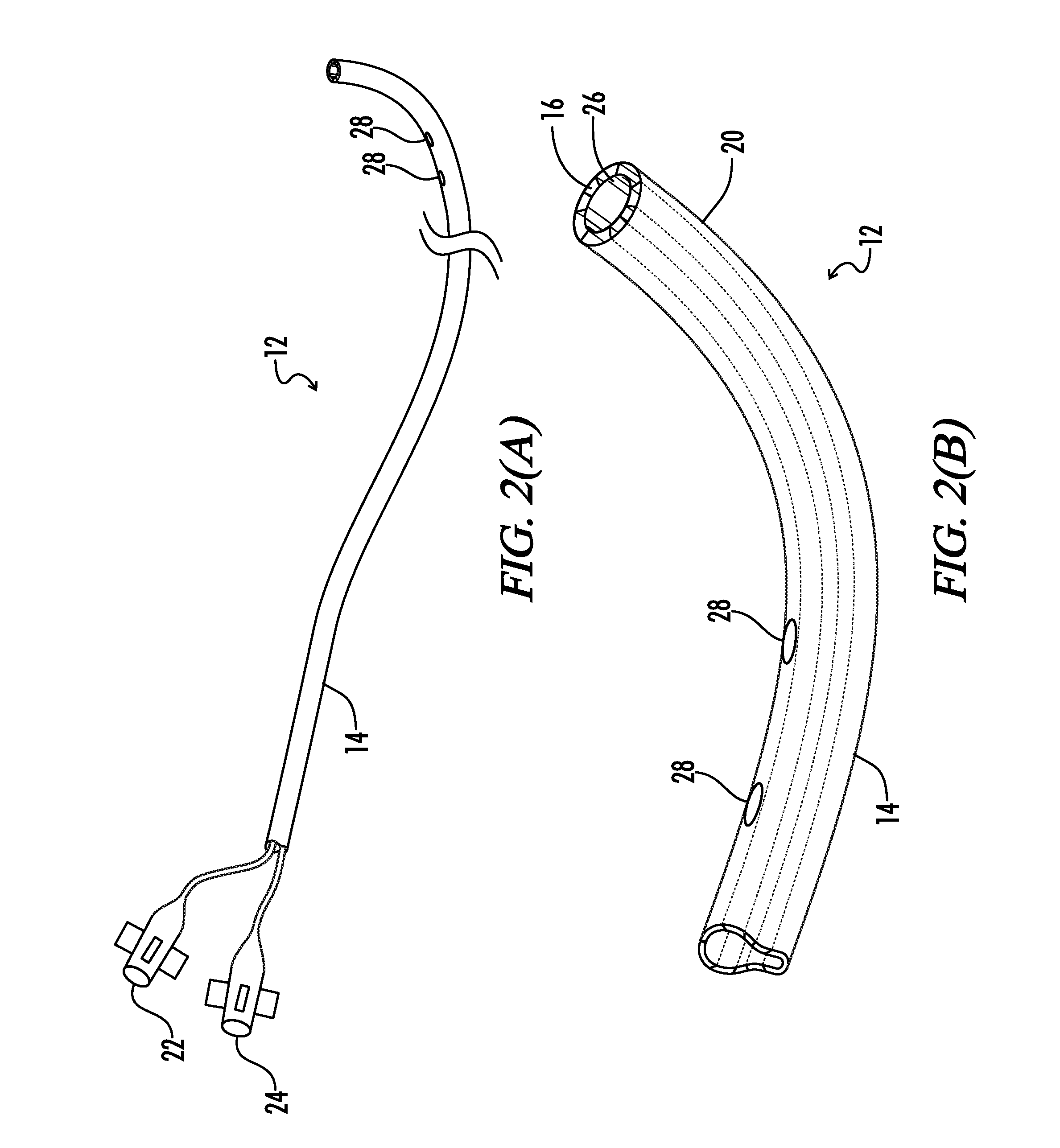
[0018]The present invention is directed toward a new family of guide catheters, such as coronary guide catheters, designed to improve upon existing guide catheters by making them more versatile and multipurpose while improving their safety and efficiency of use. The invention uses designs that employ different arrangement mechanisms to integrate orifices that are used to allow uninterrupted blood flow into the artery being accessed. The invention is composed a number of specific catheter designs that accommodate blood flow to the artery from each catheter's tip region while the catheters are in service.

[0019]The present guide catheters with gills have one or more of the following improvements or innovations integrated into the catheter: modified orifices, orifice regions, and or dye injection passages with features that enable the opening or closing of the orifices. These innovations are directed toward delivering the tracer dye at the very tip of the catheter guide with gills at al...


PUM


Abstract

A guide catheter has an inlet orifice that allows blood to enter an interior passage of the catheter. A valve is positioned next to the inlet orifice that selectively opens and closes the inlet orifice. The catheter includes a dye passage that transports dye from a proximal end of the catheter to a dye outlet orifice. The dye passage may be formed in a unitary tubular member, a partitioned tubular member or in the clearances of a double-walled catheter. A valve may also be positioned next to the dye outlet orifices that selectively opens and closes the orifices. The valves are preferably kidney-shaped expandable bladders or pressure valves. A capillary tube connected to the expandable bladder functions to inflate and deflate the expandable bladder. The expandable bladders and capillary tubes are incorporated into the wall of the catheter.

Description

CROSS-REFERENCES TO RELATED APPLICATIONS[0001]This application claims priority from co-pending U.S. Provisional Patent Application Ser. No. 61 / 966,315 filed Feb. 21, 2014, entitled “Coronary Guide Catheter with Gills” which is hereby incorporated by reference.STATEMENT REGARDING FEDERALLY SPONSORED RESEARCH OR DEVELOPMENT[0002]Not ApplicableREFERENCE TO SEQUENCE LISTING OR COMPUTER PROGRAM LISTING APPENDIX[0003]Not ApplicableBACKGROUND OF THE INVENTION[0004]Arterial catheters are designed and constructed to help cardiologists gain access to heart arteries for diagnostics and other purposes. Catheters are generally constructed of a thin walled linear tubing having an inlet fitting and a slightly curved tip region or hooked end. There are slight, variations in the designs of the most frequently used heart catheters that provide functional differences.[0005]Some catheters are also used to inject tracer dye into specific locations in heart arteries to allow imaging and visualization of ...

Claims


Application Information

Patent Timeline
Patent Type & Authority Applications(United States)
IPC IPC(8): A61M25/00A61M5/00
CPCA61M5/007A61M25/0075A61M25/0071A61M31/005A61M2025/0079
Inventor VAKILI, AHMAD D.GUPTA, DINESH
Owner VAKILI AHMAD D
Why Eureka
Try Eureka