
Battery temperature regulating device

Active Publication Date: 2015-09-24
TOYOTA JIDOSHA KK
View PDF14 Cites 34 Cited by
  • Summary
  • Abstract
  • Description
  • Claims
  • Application Information

AI Technical Summary

Benefits of technology

The present invention is about a device that regulates the temperature of a battery in a vehicle. The device allows the battery to function as a heat accumulation unit, which helps to reduce unnecessary power consumption during external charging. This results in a longer range of travel for the vehicle. The device targets a higher temperature for the battery when heat accumulation is unnecessary, which helps to suppress power consumption. Additionally, while the battery is charging, it can be preheated using the power it receives, without reducing the amount of electricity stored in the battery. Overall, this invention allows the battery to function as a heat accumulation unit while eliminating unnecessary power consumption during external charging.

Problems solved by technology

If the battery is not charged and / or discharged at a proper temperature, it will prevent the battery to exhibit its performance sufficiently and will adversely affect the service life thereof, and thereby, a temperature regulating device for the battery is mounted on such vehicle.
Thus, sufficient studies have not been made on making effective utilization of this heat.
Particularly, since the heat from engine cannot be utilized to warm the compartment of a hybrid vehicle when the engine thereof is stopped and the heat from engine is not available for an electric vehicle without an engine, it is necessary to convert the electrical energy that is accumulated in the battery into heat so as to warm the passenger compartment, which consequently shortens the available traveling distance.
Raising the temperature of the battery during external charging is advantageous from the viewpoint of increasing the available travelling distance, however, raising the temperature of the battery to the same temperature without variation during external charging is disadvantageous from the viewpoint that additional power will be consumed.

Method used


Image

  • Battery temperature regulating device
  • Battery temperature regulating device
  • Battery temperature regulating device

Examples


Embodiment Construction

[0022]Hereinafter, embodiments of the present invention will be described in detail with reference to the drawings. It should be noted that in the drawings, the same or corresponding parts will be assigned with the same reference signs, and the description thereof will not be repeated.

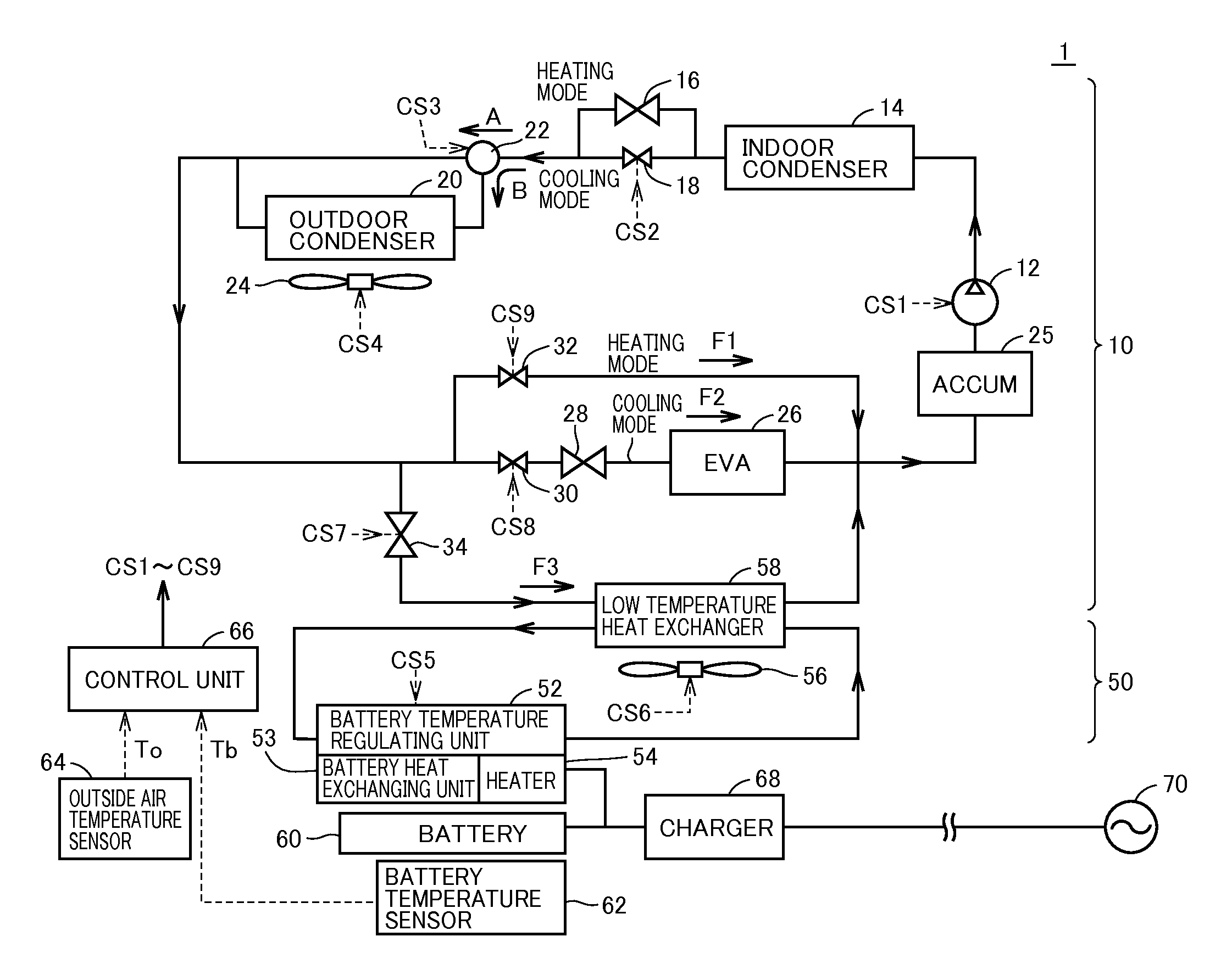
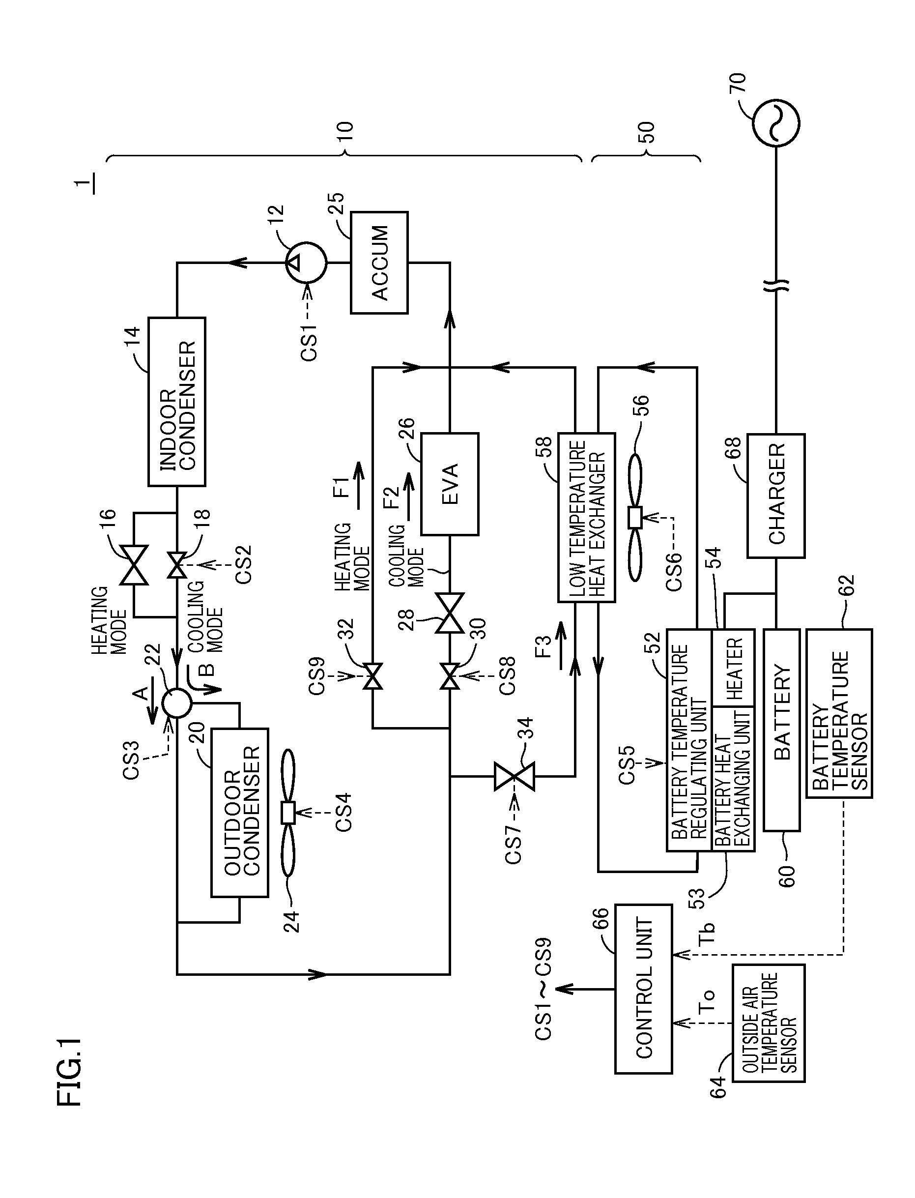
[0023]FIG. 1 is a diagram illustrating a configuration of a vehicle mounted with the battery temperature regulating device according to the present embodiment. Referring to FIG. 1, a vehicle 1 includes an air conditioning system 10, a battery temperature regulating device 50, a battery 60, and a charger 68.

[0024]Charger 68 receives power from an external power supply 70 and supplies the received power to battery 60. Although charger 68 is illustrated as receiving the power from an external power supply through a charging cable equipped with an inlet (not shown), it is acceptable that the vehicle is configured to perform power exchange in an non-contact manner through an electromagnetic field or the lik...


PUM


Abstract

A battery temperature regulating device is provided with a low temperature heat exchanger configured to allow heat exchange with the air conditioning system, a battery temperature regulating unit configured to allow heat exchange with the low temperature heat exchanger so as to regulate the temperature of the battery to approach a target temperature, and a control unit configured to control the battery temperature regulating unit. In the case where the charging is performed from the power supply external to the vehicle, the control unit determines whether or not it is necessary to accumulate heat in the battery, and in the case where it is determined that the heat accumulation is necessary, the control unit sets the target temperature of the battery during charging higher than that in the case where it is determined that the heat accumulation is unnecessary.

Description

[0001]This non-provisional application is based on Japanese Patent Application 2014-056361 filed on Mar. 19, 2014 with the Japan Patent Office, the entire contents of which are hereby incorporated by reference.BACKGROUND OF THE INVENTION[0002]1. Field of the Invention[0003]The present invention relates to a battery temperature regulating device, and in particular, relates to a battery temperature regulating device mounted on a vehicle including a battery configured to allow charging from a power supply external to the vehicle.[0004]2. Description of the Background Art[0005]An electric vehicle or a hybrid vehicle is mounted with a drive battery configured to supply power to a drive motor. If the battery is not charged and / or discharged at a proper temperature, it will prevent the battery to exhibit its performance sufficiently and will adversely affect the service life thereof, and thereby, a temperature regulating device for the battery is mounted on such vehicle.[0006]In WO 2012 / 00...

Claims


Application Information

Patent Timeline
IPC IPC(8): B60L11/18
CPCB60L11/1874B60L11/1816B60L11/1875B60H1/00278H01M2220/20H01M10/486B60L1/003B60L1/02B60L2240/34B60L2240/545B60L2240/662B60L2240/80B60L2250/14H01M10/625H01M10/615H01M10/633H01M10/657H01M10/663H01M10/6568H01M10/635H01M10/613Y02T90/16Y02T10/7072Y02T90/14B60H1/00921B60H1/143B60H2001/00928B60H2001/00949B60L53/14B60L58/24B60L58/26B60L58/27B60H2001/00307Y02T10/70Y02T10/72Y02E60/10H01M10/443H01M10/61H02J7/007192
Inventor ARAI, KUNIHIKOKAWAKAMI, YOSHIAKI
Owner TOYOTA JIDOSHA KK
Learn More