Variable rate assembly for a brake system for bicycle

Active Publication Date: 2015-09-24
SRAM CORPORATION
View PDF6 Cites 13 Cited by
  • Summary
  • Abstract
  • Description
  • Claims
  • Application Information

AI Technical Summary

Benefits of technology

[0004]The invention provides linkages for a brake system, for example, in a hydraulic brake system for a bicycle. The invention relates to an assembly for brake actuation systems for bicycles and includes a variable rate linkage brake arrangement and lever preferably

Problems solved by technology

Typical hydraulic brake systems that have a linear rate of travel of the piston relative to the travel of the lever blade require an undesirable amount of lever travel before braking occurs, i.e., a significant amount of “dead band.” Most hydraulic brake systems do not

Method used


Image

  • Variable rate assembly for a brake system for bicycle
  • Variable rate assembly for a brake system for bicycle
  • Variable rate assembly for a brake system for bicycle

Examples


Embodiment Construction

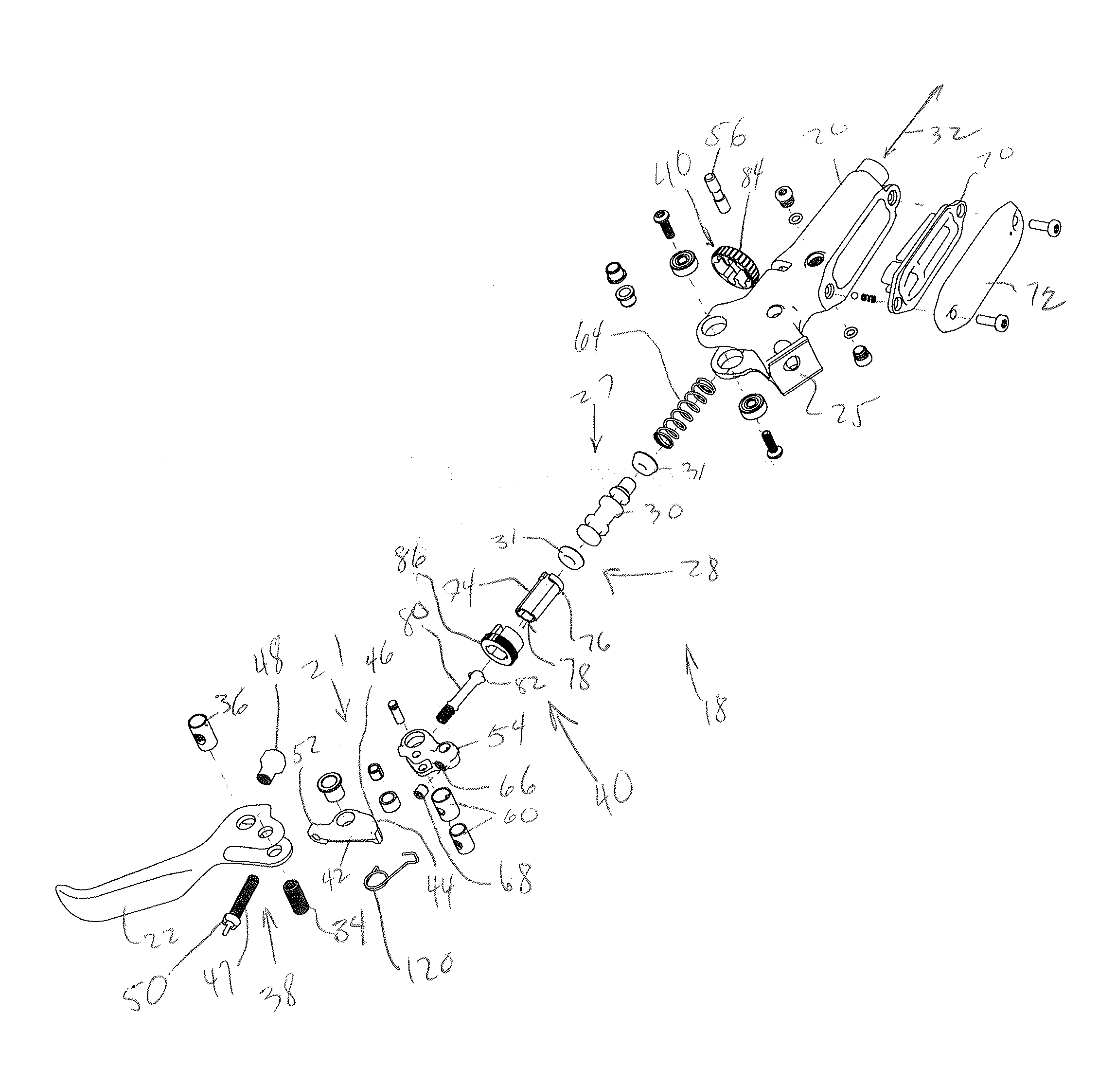
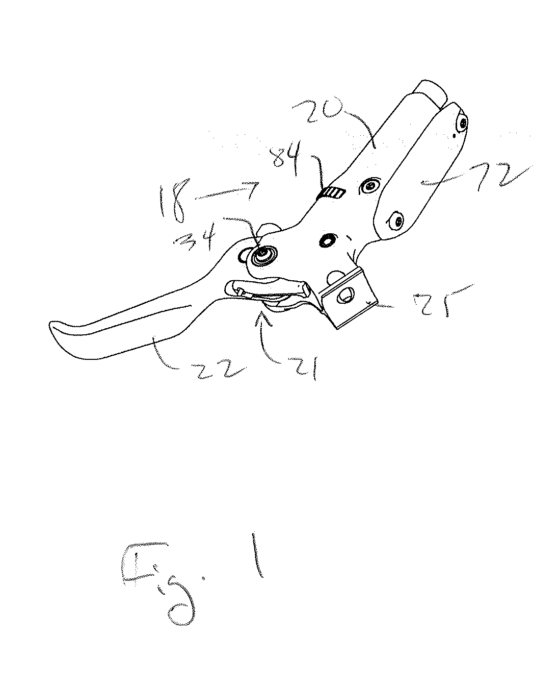
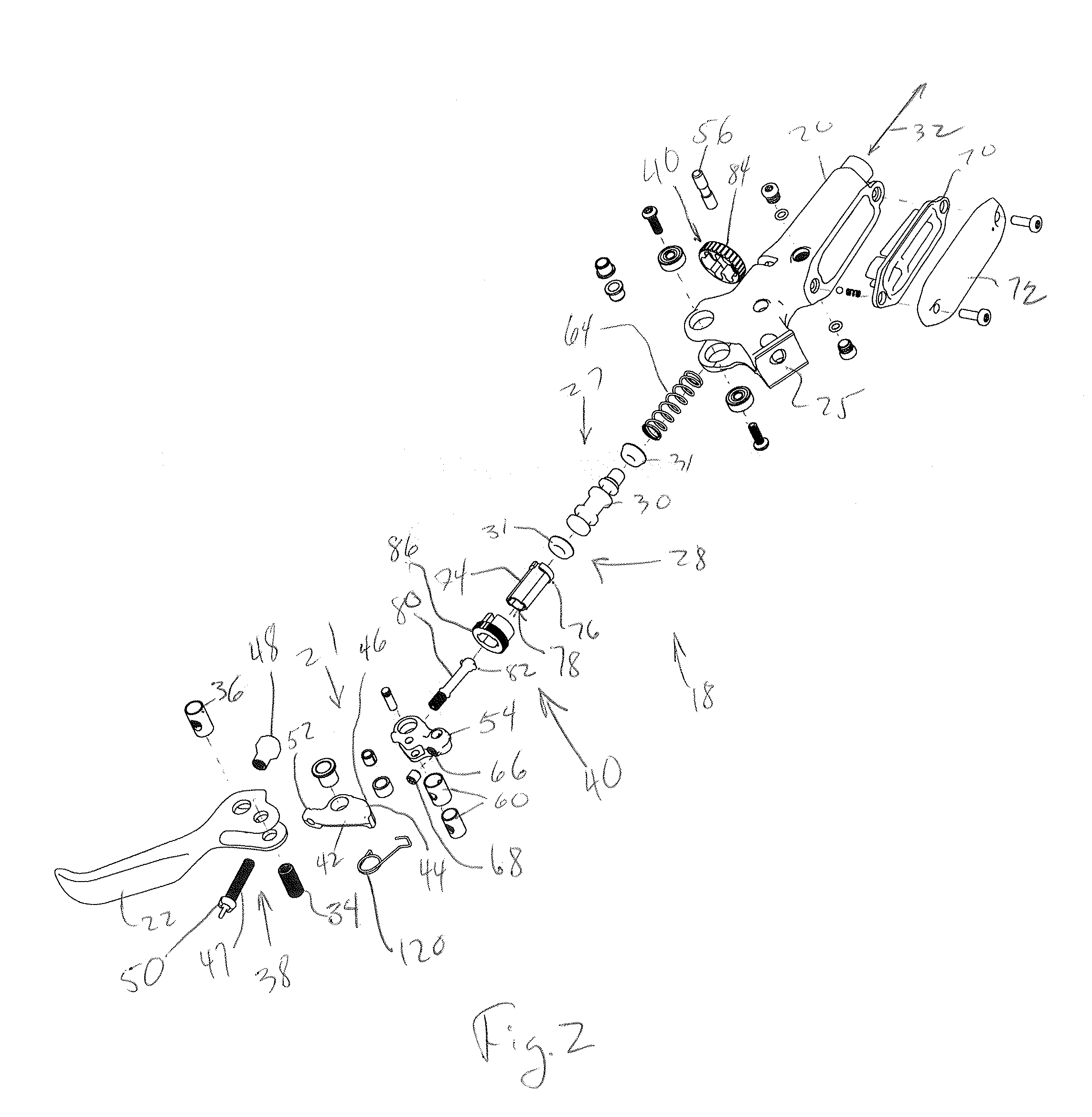
[0020]Preferred embodiments of the invention will herein be described with reference to the drawings. It will be understood that the drawings and descriptions set out herein are provided for illustration only and are not for the purpose of limiting the invention as defined by the claims appended hereto and any and all their equivalents.

[0021]In the following, the construction of a brake assembly is described, which according to an embodiment may be constructed or arranged to operate an otherwise conventional hydraulic brake system (not shown). In the described embodiment, in its most general form, the invention provides a brake assembly and system constructed to produce a desired variable lever ratio, i.e., one that is non-linear, which will be described in detail hereinbelow. Also, the invention contemplates the provision of a mechanism to adjust the dead band in the assembly without affecting the desired non-linear nature of the brake assembly. The inventive brake assembly may be ...


PUM


Abstract

A brake assembly for a hydraulic brake system of a handlebar-steered vehicle, the brake assembly including a housing mountable to a handlebar of the vehicle and having a chamber formed therein. The brake assembly is provided with a variable rate linkage. A piston assembly is received and axially guided within the chamber and is provided with a piston adjustment mechanism that does not affect the function of the variable rate linkage.

Description

BACKGROUND OF THE INVENTION[0001]A hydraulic brake system for a bicycle typically includes a hydraulic brake actuation device, a rotor attached to a wheel of the bicycle and a brake caliper operatively connected to the brake actuation device. The caliper is responsive to changes in hydraulic pressure generated by the brake actuation device to urge brake pads into contact with the rotor and effect braking.[0002]When the brake actuation device is initially actuated, no braking forces are generated because a gap must be closed between the brake pads and the rotor. Typical hydraulic brake systems that have a linear rate of travel of the piston relative to the travel of the lever blade require an undesirable amount of lever travel before braking occurs, i.e., a significant amount of “dead band.” Most hydraulic brake systems do not address dead band and changes in dead band from pad wear, and except for set-up procedures, there have been few efforts to develop mechanisms that are adjustab...

Claims


Application Information

Patent Timeline
IPC IPC(8): B62L3/02
CPCB62L3/023
Inventor SNEAD, BRADEN T.
Owner SRAM CORPORATION
Why Eureka
Try Eureka