This helps you quickly interpret patents by identifying the three key elements:
Problems solved by technology
Method used
Benefits of technology
Benefits of technology
The present invention provides an overlock sewing machine that allows for looper threading with one hand and offers favorable operating feelings. It is easy to determine whether the machine is in a sewing enabled state or not.
Problems solved by technology
However, in the device of Patent Document 3, a user needs to operate a member including the groove cam in a sliding manner, which lead to negative impression of operability.
More particularly, in the device of Patent Document 3, large load changes are caused when the control pin runs onto a plurality of cam positions, and these load changes are directly caught by the user.
Particularly for users who operate this device for the first time, there were cases in which they felt uneasy whether they should proceed with further operations since sliding of the operating member felt suddenly heavier.
Method used
Image
Click on the blue label to locate the original text in one second.
Reading with bidirectional positioning of images and text.
Examples
first embodiment
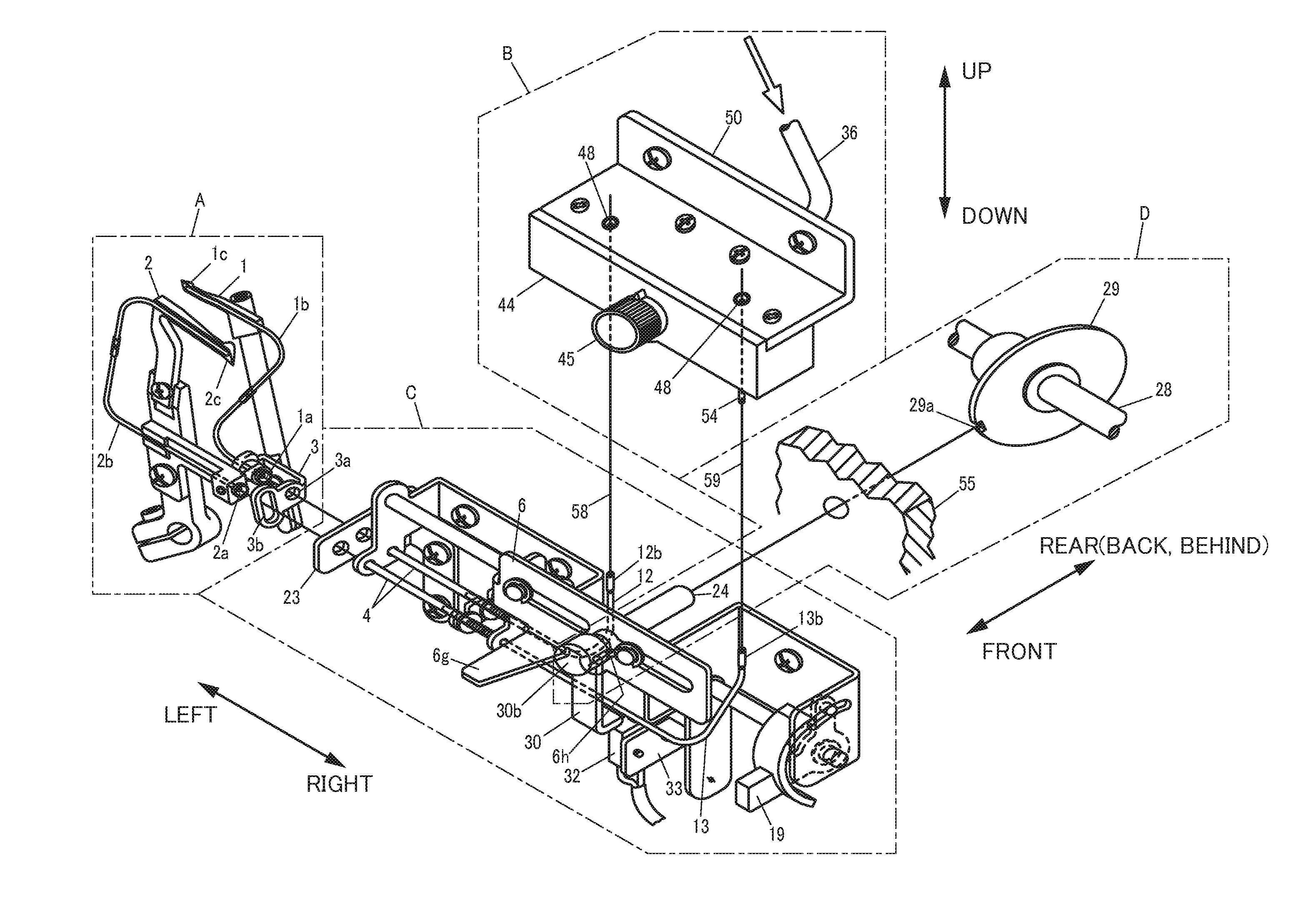
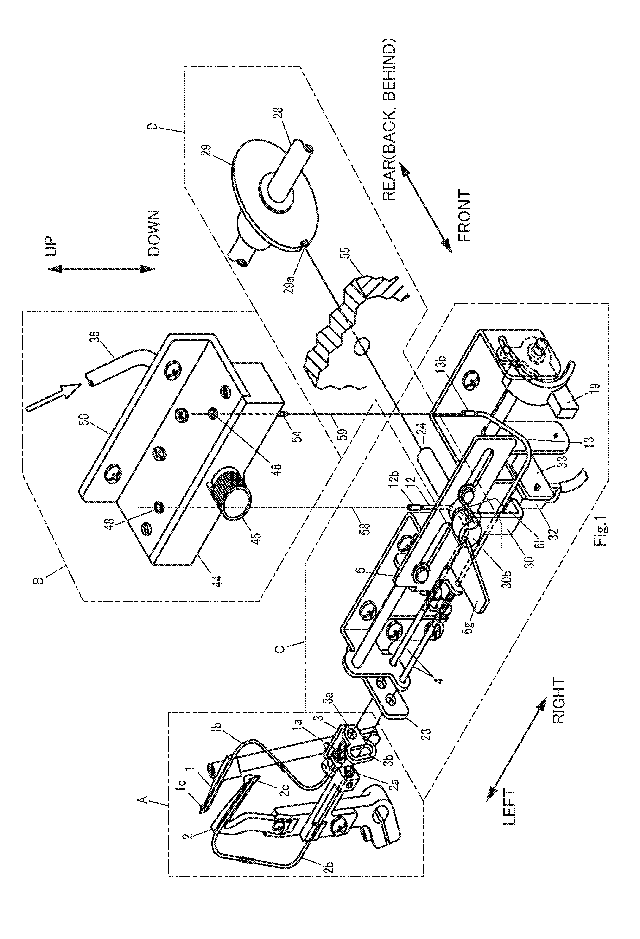
[0063]FIG. 1 is a perspective view of main portions for showing an embodiment of an overlock sewing machine according to the present invention.
[0064]In this respect, each of the drawings including FIG. 1 indicated hereinafter are schematically illustrated drawings and sizes and shapes of respective portions are shown in suitably exaggerated form for ease of understanding.
[0065]Further, while explanations are made upon indicating specific numerical values, shapes and materials in the following explanations, they may be suitably changed.
[0066]Moreover, for ease of understanding and for convenience sake, explanations will be made by suitably using the six directions of front (or near), rear (or back, behind), left, right, up and down as indicated by arrows in FIG. 1. However, these directions are not to limit the arrangement of the invention.
[0067]In the present embodiment, explanations will be made by giving a case of an overlock sewing machine comprising two loopers (upper looper 1, ...
modified embodiment
[0183]The present invention is not limited to the above explained embodiment but various modifications and changes are possible which are also included in the present invention.
[0184](1) In the present embodiment, the relationship between the main shaft fixing outer shaft 24 as the first shaft and the main shaft fixing inner shaft 26 as the second shaft has been explained while citing an example in which the second shaft side is located inside. The present invention is not limited to this arrangement, and it can be arranged in that the first shaft side is inside and the second shaft side is outside. Further, the invention is not limited to an embodiment in which one shaft is inserted into the interior of the other shaft, but any arrangement in which both members are relatively movable in an axial direction would do, and any embodiment including, for instance, a case in which a rail-like guide portion is provided, would do.
[0185](2) In the present embodiment, explanations have been m...
PUM
Abstract
An overlock sewing machine includes a main shaft fixing operating arm provided with a shaft pin engaging portion that engages with a fixing inner shaft pin and an arm provided to be operable by a user which are integrally rockable within a specified range, and further includes a main shaft fixing operating spring which urging direction is switched in both directions of an rocking direction by exceeding a neutral point by the rocking movements of the main shaft operating arm and the arm. Further, a switching cam ring is fixed to the main shaft fixing operating shaft that obtains driving force upon abutment of a slide plate pin of the slide plate to rotate the main shaft fixing operating shaft.
Description
CROSS REFERENCE TO RELATED APPLICATIONS[0001]This application is based on and claims the benefit of priority to Japanese Patent Application No. 2014-055393 filed on Mar. 18, 2014, the contents of which are hereby incorporated by reference in their entirety.TECHNICAL FIELD[0002]The present invention relates to an overlock sewing machine in which looper threads can be threaded to loopers utilizing power of air.BACKGROUND ART[0003]An overlock sewing machine is provided with a plurality of loopers, and since it is necessary to thread each of the loopers with respectively different looper threads, threading operations were troublesome.[0004]Patent Document 1 discloses a device for threading a thread to a hollow looper point using compressed air.[0005]Patent Document 2 discloses a compressed airpath switching device corresponding to a plurality of loopers.[0006]These techniques have enabled easy threading operations of looper threads to loopers.[0007]On the one hand, the devices disclose...
Claims
Application Information
Patent Timeline
Application Date:The date an application was filed.
Publication Date:The date a patent or application was officially published.
First Publication Date:The earliest publication date of a patent with the same application number.
Issue Date:Publication date of the patent grant document.
PCT Entry Date:The Entry date of PCT National Phase.
Estimated Expiry Date:The statutory expiry date of a patent right according to the Patent Law, and it is the longest term of protection that the patent right can achieve without the termination of the patent right due to other reasons(Term extension factor has been taken into account ).
Invalid Date:Actual expiry date is based on effective date or publication date of legal transaction data of invalid patent.

