
Method of autheticating interlock function of PLC control program using smv

a technology of interlock function and control program, which is applied in the direction of program control, electric programme control, instruments, etc., can solve the problems of large losses, loss of life and destruction of expensive facilities, and malfunction of automated production system, so as to prevent an erroneous operation

Inactive Publication Date: 2015-09-24
UDMTEK
View PDF0 Cites 4 Cited by
  • Summary
  • Abstract
  • Description
  • Claims
  • Application Information

AI Technical Summary

Benefits of technology

The present invention provides a method for verifying the interlock function of a PLC control program using a symbolic model verifier (SMV) to prevent errors in an automated production system. The method extracts and modifies or compensates the signals and programs that cause errors to avoid inspecting the entire PLC control program when an error occurs. This saves time and resources and ensures the system operates efficiently and without errors.

Problems solved by technology

When the PLC control program is not properly designed, there may be a malfunction in the automated production system, which may cause great losses such as losses of life and the destruction of expensive facilities.
Generally, particular signals used in the PLC control program, for example, output signals for driving particular facilities are turned on at the same time, thereby causing the malfunction of the automated production system.
However, since the PLC control program includes several thousands of signals and complicated logics, it is not easy for a PLC programmer to check one by one whether the interlock function is perfectly provided to prevent the erroneous situation in which particular signals are turned on (ON) at the same time.
However, when the PLC control program is verified through simulations and test runs, since the number of signal statuses to be inspected increases geometrically, it is impossible to inspect all cases.

Method used

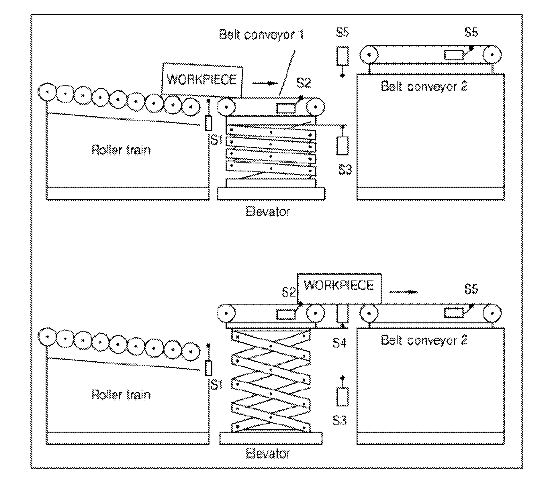
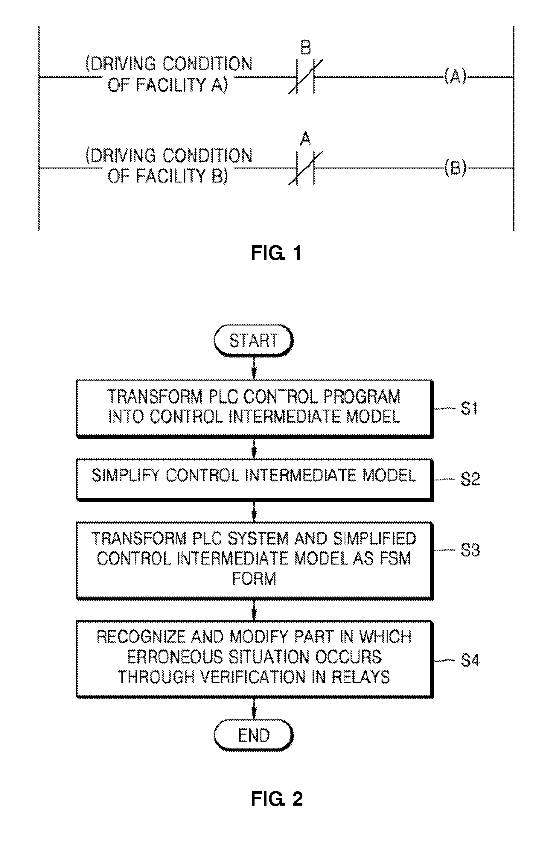
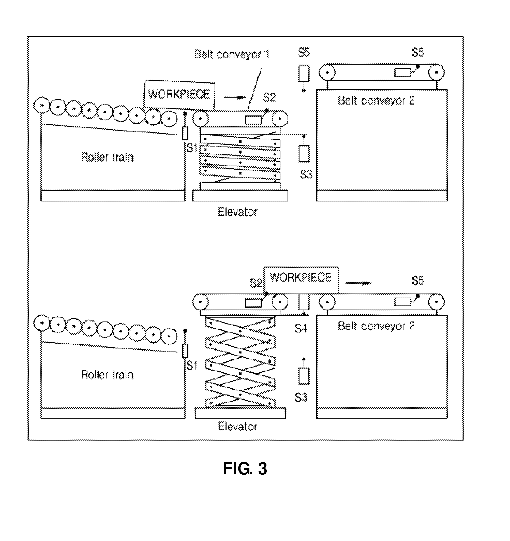

Image

  • Method of autheticating interlock function of PLC control program using smv
  • Method of autheticating interlock function of PLC control program using smv
  • Method of autheticating interlock function of PLC control program using smv

Examples


Embodiment Construction

[0026]Hereinafter, exemplary embodiments of the present invention will be described in detail with reference to the attached drawings.

[0027]The embodiments of the present invention are provided to more perfectly explain the present invention to a person of ordinary skill in the art. The following embodiments may be modified into various other forms, and the scope of the present invention is not limited to following embodiments. The embodiments are provided to allow the present disclosure to be more faithful and full and to perfectly transfer the inventive concept to those skilled in the art.

[0028]Terms used herein are to describe particular embodiments but will not limit the present invention. As used herein, the singular forms are intended to include the plural forms as well, unless the context clearly indicates otherwise. It will be further understood that the terms “comprises” and / or “comprising” used herein specify the presence of stated shapes, numbers, operations, elements, an...


PUM


Abstract

Provided is a method of verifying an interlock function of a PLC control program which includes transforming the PLC control program into a control intermediate model, simplifying the control intermediate model using information on an output signal list of output signals among a plurality of output signals outputted from the PLC driving system as the PLC control program is driven, transforming the PLC driving system and the simplified control intermediate model into a finite state machine (FSM) form, and verifying in relays of checking whether a situation in which the output signals of the output signal list causing the erroneous situation are turned on (ON) at the same time occurs in the control intermediate model simplified to the FSM form using a symbolic model verifier (SMV) and modifying the PLC control program.

Description

TECHNICAL FIELD[0001]The present invention relates to a method of verifying interlock function of a PLC control program using a symbolic model verifier (SMV).BACKGROUND ART[0002]It is necessary to consider safety in the workplace while designing a PLC control program driven by a PLC driving system controlling an automated production system. When the PLC control program is not properly designed, there may be a malfunction in the automated production system, which may cause great losses such as losses of life and the destruction of expensive facilities.[0003]Generally, particular signals used in the PLC control program, for example, output signals for driving particular facilities are turned on at the same time, thereby causing the malfunction of the automated production system. Accordingly, the malfunction of the automated production system may be prevented by providing a PLC control program absolutely not to allow an erroneous situation defined as a state in which particular signals...

Claims


Application Information

Patent Timeline
Patent Type & Authority Applications(United States)
IPC IPC(8): G05B19/05
CPCG05B19/056G05B19/05G05B17/00
Inventor PARK, CHANG MOKWANG, GI NAM
Owner UDMTEK
Learn More