Vehicle speed measuring method

A vehicle and speed measurement technology, applied in the field of vehicle detection, can solve the problems of low detection accuracy, inability to determine whether the vehicle is the same vehicle, wrong vehicle speed, etc., to achieve the effect of improving the detection accuracy

Active Publication Date: 2016-09-21
DONGGUAN UNIV OF TECH
View PDF5 Cites 8 Cited by
  • Summary
  • Abstract
  • Description
  • Claims
  • Application Information

AI Technical Summary

Problems solved by technology

The above-mentioned magnetoresistive-based sensors have low detection accuracy when detecting vehicles and their driving speeds, and when the base station calculates the vehicle speed, it cannot determine whether the vehicles passing the upstream and downstream sensors are the same vehicle, and the vehicles may overtake during driving. The upstream and downstream nodes are not the same vehicle, the calculation of vehicle speed is wrong
Therefore, existing vehicle speed measurements have limitations

Method used


Image

  • Vehicle speed measuring method
  • Vehicle speed measuring method
  • Vehicle speed measuring method

Examples


Embodiment 1

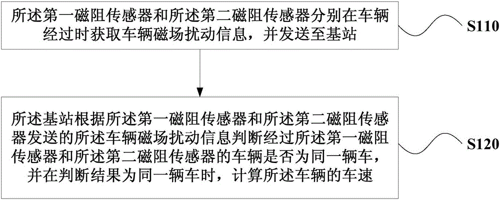
[0017] figure 1 It is a flow chart of a vehicle speed measurement method provided by Embodiment 1 of the present invention. This method is suitable for detecting the speed of vehicles on the road. Described method specifically comprises:

[0018] S110. The first magnetoresistive sensor and the second magnetoresistive sensor respectively acquire vehicle magnetic field disturbance information when the vehicle passes by, and send the information to a base station.

[0019] In the present invention, two magnetoresistive sensors are respectively arranged upstream and downstream of the lane: a first magnetoresistance sensor and a second magnetoresistance sensor. The first magnetoresistive sensor and the second magnetoresistive sensor are arranged at intervals along a direction parallel to the lane. Because when the vehicle passes each magnetoresistive sensor, the magnetic field around the magnetoresistive sensor will be disturbed, at this time, the magnetoresistive sensor acquire...

Embodiment 2

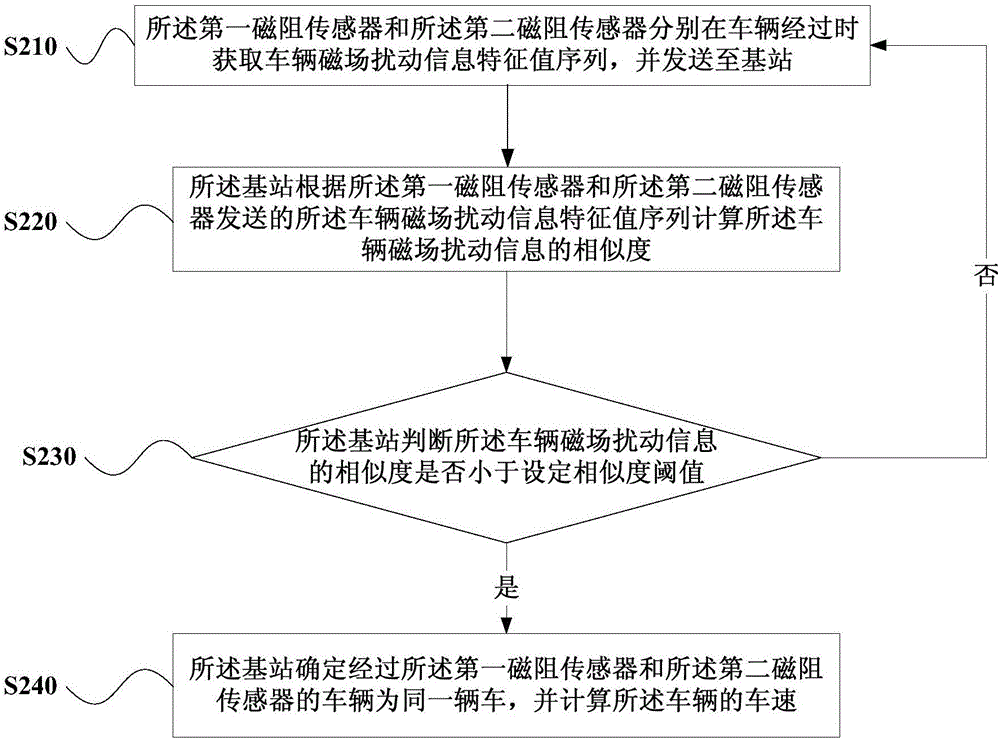
[0023] image 3 A schematic flow chart of a vehicle speed measurement method provided in Embodiment 2 of the present invention, as shown in figure 2 As shown, the method includes:

[0024] S210. The first magnetoresistive sensor and the second magnetoresistive sensor respectively acquire the characteristic value sequence of the vehicle's magnetic field disturbance information when the vehicle passes by, and send the sequence to the base station.

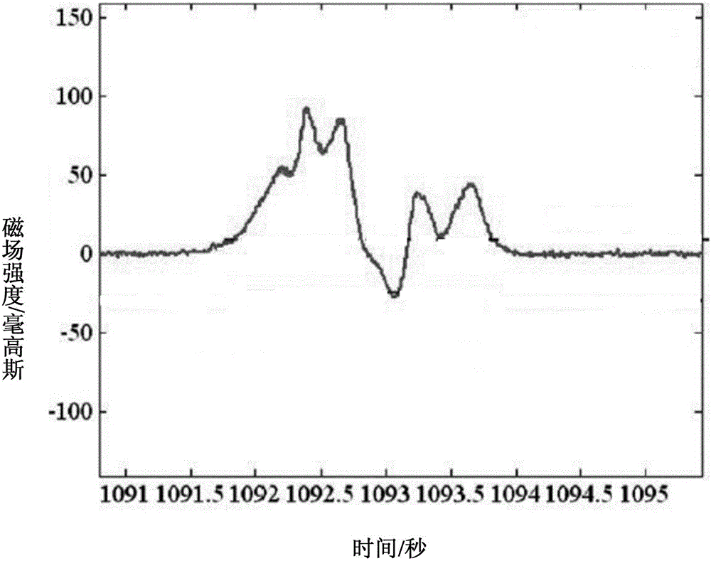
[0025] When a vehicle passes the magnetoresistive sensor, it will cause fluctuations in the surrounding magnetic field. Specifically, the first magnetoresistive sensor and the second magnetoresistive sensor can periodically sample and acquire the surrounding magnetic field strength when the vehicle passes by. And the magnetic field strength of the sampling point is composed of the characteristic value sequence of the vehicle magnetic field disturbance information and sent to the base station.

[0026] S220. The base station calcul...

Embodiment 3

[0033] Figure 4 It is a schematic flowchart of a method for measuring vehicle speed provided by Embodiment 3 of the present invention. Figure 5 A schematic diagram of the positional deployment of the first magnetoresistive sensor and the second magnetoresistive sensor provided in Embodiment 3 of the present invention, as shown in Figure 5 As shown, in the same lane, first magnetoresistive sensors p and second magnetoresistive sensors q are arranged at intervals along the direction parallel to the lane. The base station R can communicate wirelessly with the first magnetoresistive sensor p and the second magnetoresistive sensor q. In other embodiments, according to the concept of the present invention, two magnetoresistive sensors can be set in all lanes of the road, for example Figure 5 Among them, the first magnetoresistive sensor p and the second magnetoresistive sensor q are arranged in the first lane, and the third magnetoresistive sensor m and the fourth magnetoresis...


PUM


Abstract

The invention discloses a vehicle speed measuring method. A first magneto-resistive sensor and a second magneto-resistive sensor are arranged at an interval along a direction parallel to a lane direction. The method comprises: the first magneto-resistive sensor and the second magneto-resistive sensor obtain vehicle magnetic field disturbance information when a vehicle passes by and send the information to a base station; and the base station determines vehicles passing by the first magneto-resistive sensor and the second magneto-resistive sensor is the same vehicle based on the vehicle magnetic field disturbance information sent by the first magneto-resistive sensor and the second magneto-resistive sensor; and if so, the speed of the vehicle is calculated, so that the detection precision of the vehicle speed is improved.

Description

technical field [0001] Embodiments of the present invention relate to the technical field of vehicle detection, and in particular to a method for measuring vehicle speed. Background technique [0002] In recent years, the number of cars in cities has increased, and problems such as uncivilized driving and traffic congestion have become increasingly serious. Existing vehicle detection equipment, such as traffic cameras, radars, loop coil sensors, etc., has high cost, large volume, high power consumption, and difficult construction. The detection accuracy is greatly affected by weather and environment. [0003] The vehicle detection technology based on the magnetoresistive sensor has been developed rapidly because of its high detection sensitivity, not easily affected by the weather, and can be miniaturized. In the traditional vehicle speed detection system based on magnetoresistive sensors, when the vehicle passes the upstream and downstream sensors, each sensor judges wheth...

Claims


Application Information

Patent Timeline
Patent Type & Authority Applications(China)
IPC IPC(8): G08G1/042G08G1/052
CPCG08G1/042G08G1/052
Inventor 张足生袁华强
Owner DONGGUAN UNIV OF TECH
Why Eureka
Try Eureka