Compressor variable vane assembly

Active Publication Date: 2015-10-01
PRATT & WHITNEY CANADA CORP
View PDF1 Cites 39 Cited by
  • Summary
  • Abstract
  • Description
  • Claims
  • Application Information

AI Technical Summary

Benefits of technology

[0005]There is provided a method of manufacturing a variable vane assembly for a compressor of a gas turbine engine, the variable vane assembly including an inner shroud and an outer shroud radially spaced apart from each other to define therebetween an annular gas path through which a plurality of variable vanes radially extend between the inner and outer shrouds, each of the variable vanes is pivotable through a vane pivot arc about a respective span-wise vane axis and has a vane airfoil with an overhang portion disposed at a trailing edge thereof, the method comprising forming a plurality of projections on at least one of the inner and outer shrouds, the projections protruding from an annular boundary surface into the annular gas path, each of the projections being at least partially circumferentially disposed between two of said variable vanes and located adjacent the overhang port

Problems solved by technology

This can lead to greater vane tip losses, which may negatively affe

Method used


Image

  • Compressor variable vane assembly
  • Compressor variable vane assembly
  • Compressor variable vane assembly

Examples


Embodiment Construction

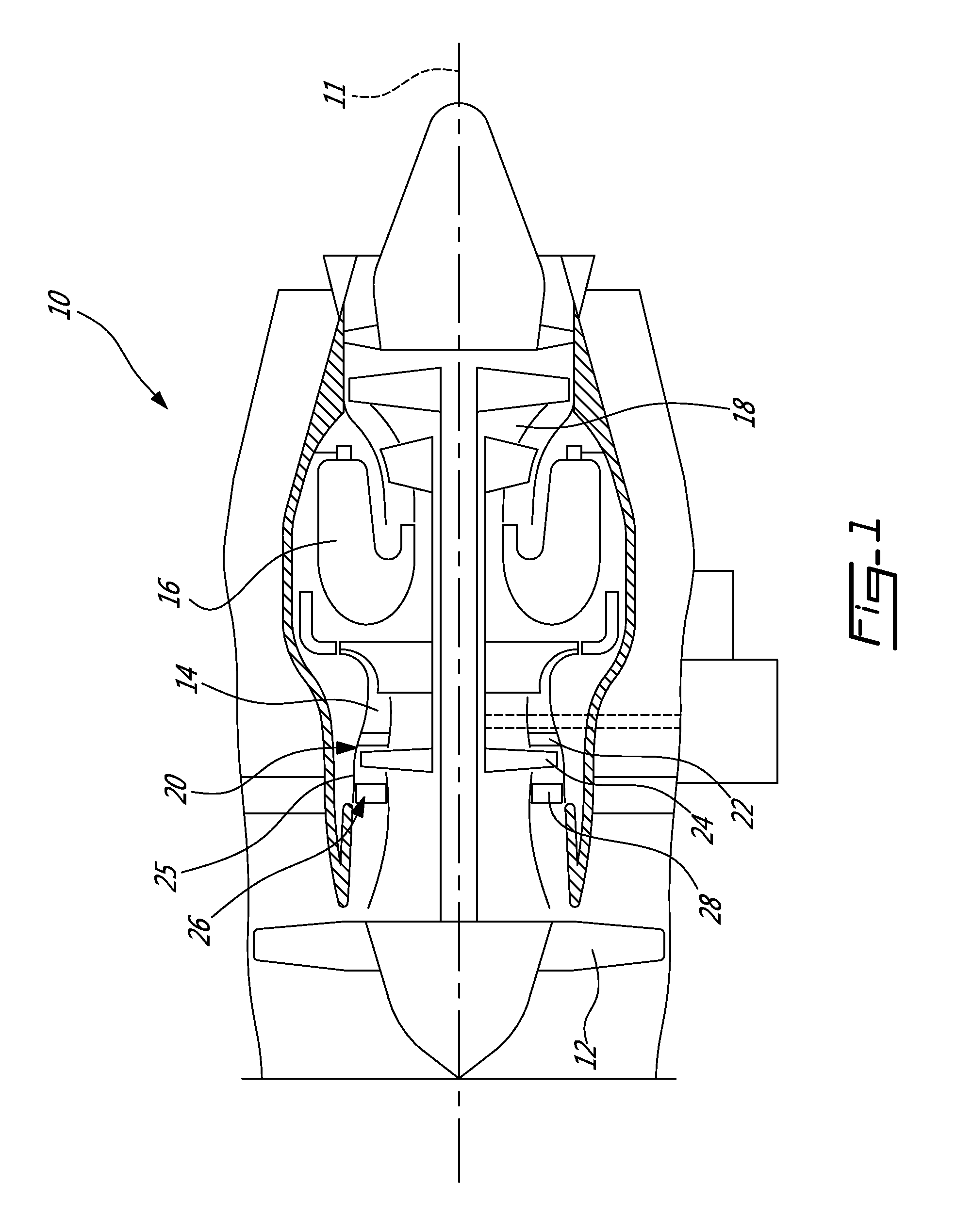
[0018]FIG. 1 illustrates a gas turbine engine 10 of a type preferably provided for use in subsonic flight, generally comprising in serial flow communication a fan 12 through which ambient air is propelled, a multistage compressor 14 for pressurizing the air, a combustor 16 in which the compressed air is mixed with fuel and ignited for generating an annular stream of hot combustion gases, and a turbine section 18 for extracting energy from the combustion gases. The compressor 14 and turbine 16 are mounted on main engine shafts which rotate about a common longitudinal axis 11 of the engine. The multistage compressor section 14 includes at least a first stage, low pressure, axial compressor 20 located downstream of the fan 12. The compressor 14 of the gas turbine engine 10 may be a multi-stage compressor, and thus may comprise several axial and / or centrifugal compressors. Although a turbofan engine is depicted and described herein, it will be understood however that the gas turbine eng...


PUM

PropertyMeasurementUnit
Weightaaaaaaaaaa
Structureaaaaaaaaaa

Abstract

A variable vane assembly for a gas turbine engine compressor and method of manufacturing same is described. A plurality of projections the inner and/or outer shroud which protruded into the annular gas path such as to ensure that a radial clearance gap, defined between the projections and a vane airfoil overhang portion, remains substantially constant throughout a substantial portion of the vane pivot arc of the variable vane. The method includes forming one cavities within the shroud, the cavities isolated from the annular gas path and disposed radially beneath at least each of the projections, and providing one or more structural reinforcing elements within the cavities.

Description

TECHNICAL FIELD[0001]The application relates generally to gas turbine engine compressors, and more particularly, to variable vanes for such compressors.BACKGROUND[0002]Variable vanes, namely vanes which are not fixed but pivot about axes such as to vary the angle of the vane airfoil, are sometimes used in gas turbine engine compressors to optimize compressor operability and / or efficiency over the compressor speed range. These variable vanes may include variable inlet guide vanes (IGV) located directly upstream of the first compressor stage, or variable vanes which form part of one or more of the subsequent downstream stages in a multistage compressor (ex: first compressor stage and / or second compressor stage, etc.). Variable vanes enable optimized compressor efficiency and / or operability by providing a close-coupled direction of the gas flow into the immediately downstream compressor rotor, and / or may introduce swirl into the compressor rotor to improve low speed operability of the ...

Claims


Application Information

Patent Timeline
IPC IPC(8): F04D29/46B33Y10/00F04D19/00F04D29/56F04D17/10
CPCF04D29/462F04D29/563B33Y10/00F04D19/00F04D17/10F01D17/162F04D29/023F04D29/164B33Y80/00F01D11/12F05D2300/603F05D2300/514F05D2300/613F05D2300/608F05D2230/31Y10T29/49245B23K2101/001B22F10/28F01D5/143B22F5/009B23K15/0086F04D29/542
Inventor MARSHALL, ANDREW R.MENHEERE, DAVID
Owner PRATT & WHITNEY CANADA CORP
Why Eureka
Try Eureka