

Power Train of Automatic Transmission
- Summary
- Abstract
- Description
- Claims
- Application Information
AI Technical Summary
Benefits of technology
Problems solved by technology
Method used
Image

Examples
Example
First Embodiment
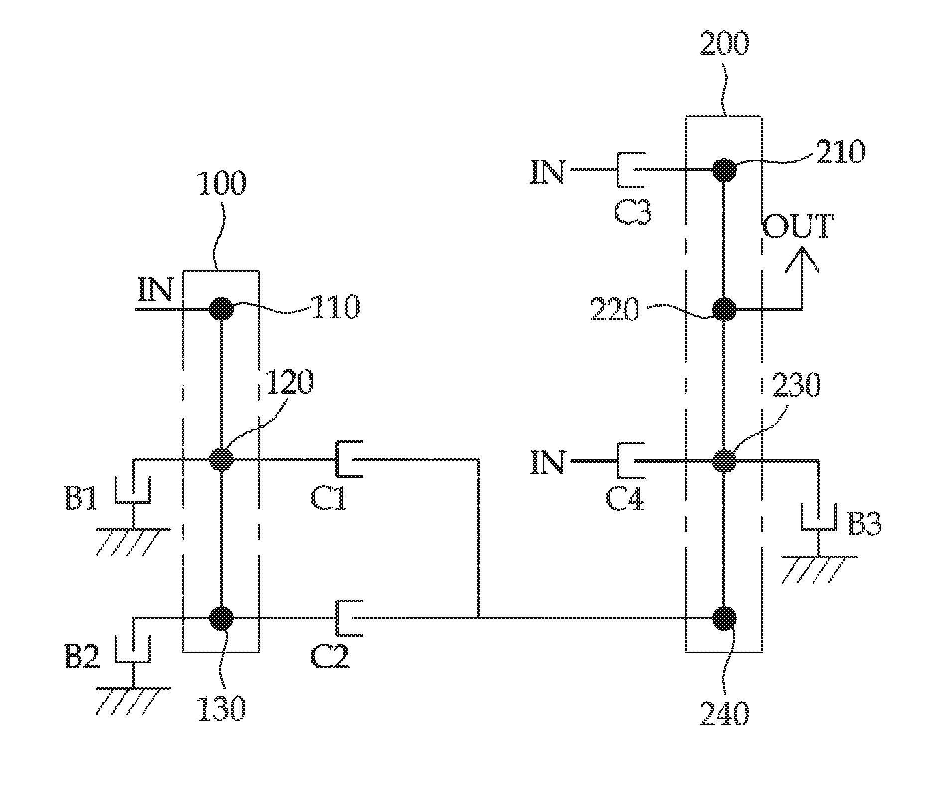
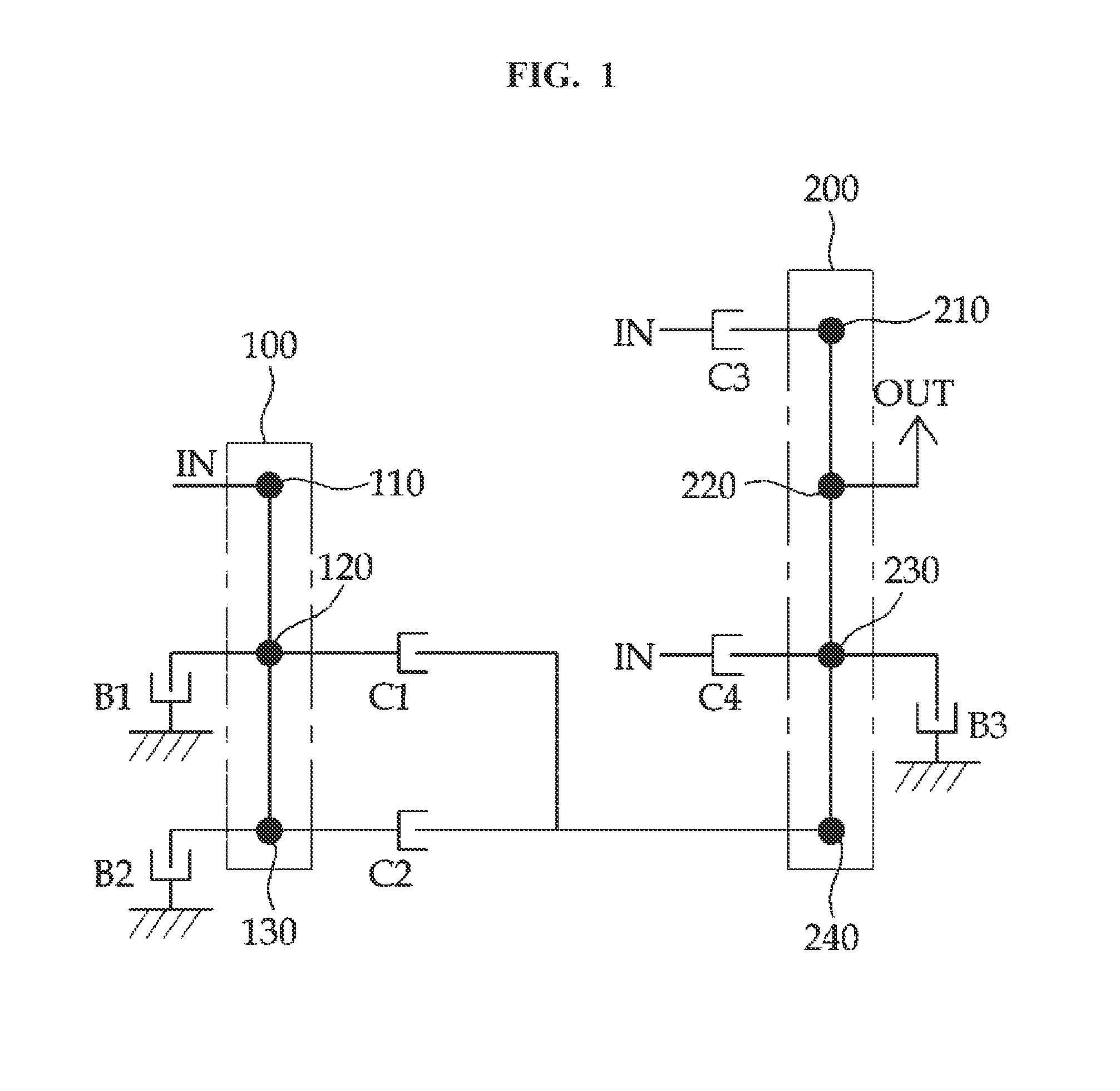
[0025]As illustrated in FIG. 1, a power train in accordance with a first embodiment of the present invention may include a first planetary gear set 100 and a second planetary gear set 200. At this time, the first and second planetary gear sets 100 and 200 may be selectively connected and controlled through three brakes B1 to B3 and four clutches C1 to C4.
[0026]The first planetary gear set 100 may include three rotating elements, that is, first to third rotating elements 110 and 130 which are engaged with each other. In particularly, the first rotating element 110 at an outer side may be connected to an input shaft IN at all times. At this time, “outer” may indicate a sun gear of the planetary gear as the fastest component.
[0027]The power transmission and interruption of the second and third rotating elements 120 and 130 may be controlled through the brakes B1 and B2 and the clutches C1 and C2, respectively. The second and third rotating elements 120 and 130 may corre...
Example
Second Embodiment
[0034]In a second embodiment of the present invention, the same components as those of the first embodiment are represented by like reference numerals, and the detailed descriptions thereof are omitted herein.
[0035]As illustrated in FIG. 4A, the power train in accordance with the second embodiment of the present invention may further include a one-way clutch OWC which is provided at an inner rotating element forming the first planetary gear set 100, that is, the second rotating element 120.
[0036]In particular, the one-way clutch OWC may control the second rotating element 120 at the first speed stage as depicted in Table 2 below, thereby preventing a slip at starting.
TABLE 2SpeedClutchBrakestageC1C2C3C4B1B2B3OWC1○○○○2○○○3○○○4♦○♦5○○○6○○○7○○○8♦○♦9○○○R○○○♦ and represent that the same shapes are coupled to form a gear shift stage.
[0037]FIG. 5 illustrates a speed map which is obtained when the clutches C1 to C4, the brakes B1 to B3, and the one-way clutch OWC are o...
Example
Third Embodiment
[0038]As illustrated in FIG. 7, a power train in accordance with a third embodiment of the present invention may include a single pinion planetary gear 100′ replacing the first planetary gear set and a stacked planetary gear 200′ replacing the second planetary gear set, as a planetary gear set.
[0039]The single pinion planetary gear 100′ may include three rotating elements, that is, a sun gear S1, a ring gear R1, and a carrier Ca1, as a single planetary gear. At this time, the sun gear S1 may be connected to the input shaft IN.
[0040]The power transmission and interruption of the ring gear R1 and the carrier Ca1 may be controlled through the brakes B1 and B2 and the clutches C1 and C2, respectively. At this time, the brakes B1 and B2 and the clutches C1 and C2 may control the ring gear R1 and the carrier Ca1 such that the same operation as the above-described first embodiment can be performed.
[0041]The stacked planetary gear 200′ may have a structure in which a pair of...
PUM
 Abstract
Description
Claims
Application Information