Coolant supplying module

a technology of cooling module and supply module, which is applied in the direction of electric propulsion mounting, machines/engines, electric propulsion generators, etc., can solve the problems of increased manufacturing cost, increased weight, and difficulty in mounting, and achieves improved spatial utility of engine compartment, convenient mounting, and efficient connection to connection pipes

Active Publication Date: 2021-07-15
HYUNDAI MOTOR CO LTD +1
View PDF0 Cites 2 Cited by
  • Summary
  • Abstract
  • Description
  • Claims
  • Application Information

AI Technical Summary

Benefits of technology

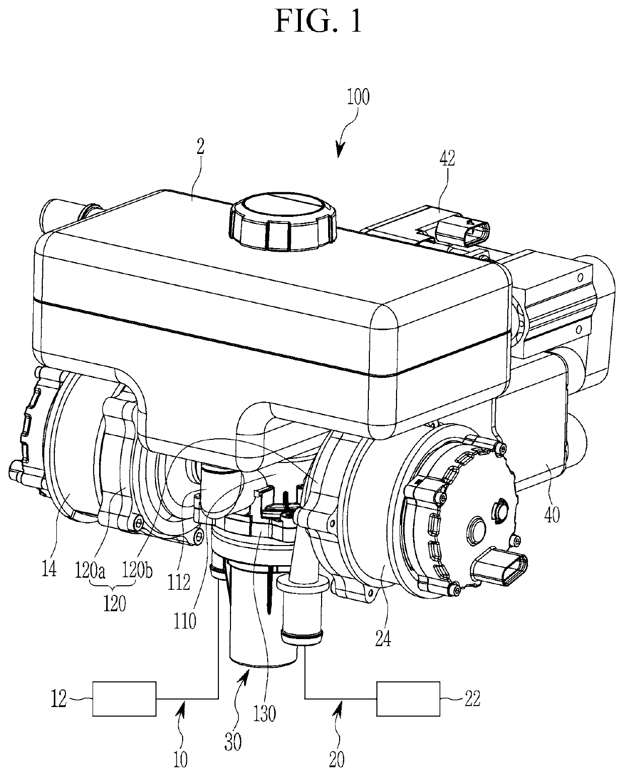
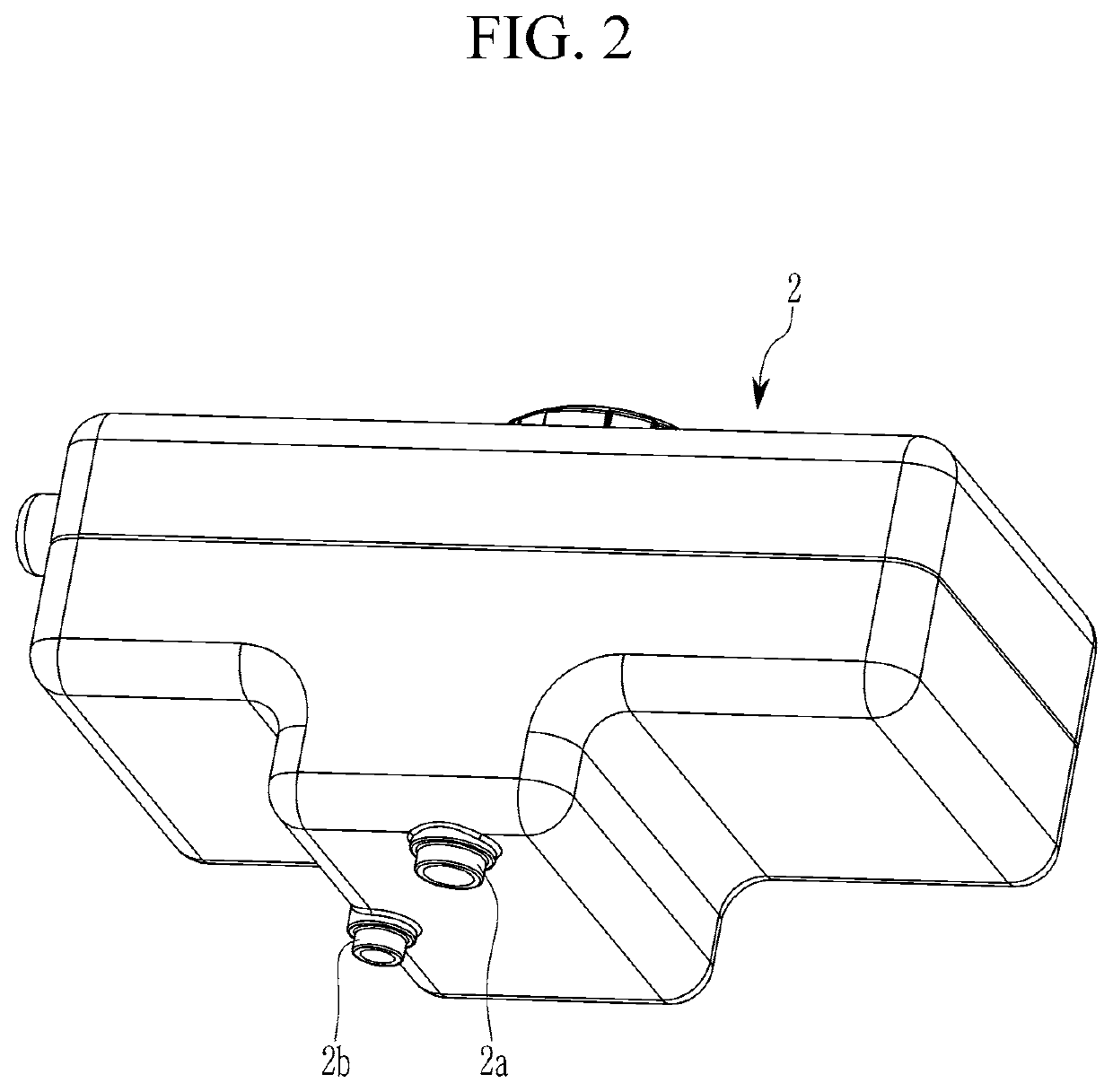
[0024]According to a coolant supplying module according to an exemplary embodiment of the present invention, since the coolant is supplied from the shared reservoir tank to both the electrical component cooling circuit and the battery cooling circuit and various constituent elements are easily mounted, spatial utility of an engine compartment may be improved.
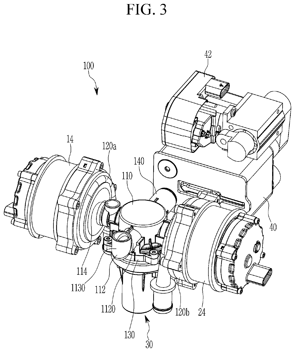
[0025]An exemplary coolant supplying module may directly mount the first and second water pumps for supplying the coolant to the electrical component cooling circuit and the battery cooling circuit and may be efficiently connected to connection pipes. Therefore, a layout of connection pipes may be simplified, and mountability and maintainability may be improved.
[0026]When the coolant valve is operated to change the flow path of the coolant, it is possible to prevent the first water pump 14 from being damaged due to cavitation by preventing an instantaneous lack of a coolant and a generating of an air bubbles.
[0027]Furthermore, required number of separate parts realizing the layout of the connection pipes may be minimized, decreasing weight and cost, and improving productivity by reducing required assembly processes.

Problems solved by technology

Accordingly, as two reservoir tanks used to each cooling circuit may be provided, they are difficult to be mounted in a narrow engine compartment, and a manufacturing cost is increased due to the increasing of the constituent elements.
Also, the weight is increased due to the increasing of the constituent elements and productivity may deteriorate by the increasing of a mounting time of each reservoir tank.

Method used


Image

  • Coolant supplying module
  • Coolant supplying module
  • Coolant supplying module

Examples


Embodiment Construction

[0036]Reference will now be made in detail to various embodiments of the present invention(s), examples of which are illustrated in the accompanying drawings and described below. While the present invention(s) will be described in conjunction with exemplary embodiments of the present invention, it will be understood that the present description is not intended to limit the present invention(s) to those exemplary embodiments. On the other hand, the present invention(s) is / are intended to cover not only the exemplary embodiments of the present invention, but also various alternatives, modifications, equivalents and other embodiments, which may be included within the spirit and scope of the present invention as defined by the appended claims.

[0037]An exemplary embodiment of the present invention will hereinafter be described in detail with reference to the accompanying drawings.

[0038]Exemplary embodiments included in the exemplary embodiment and the constructions depicted in the drawin...


PUM

PropertyMeasurementUnit
energy efficiencyaaaaaaaaaa
chemical reaction energyaaaaaaaaaa
electrical energyaaaaaaaaaa

Abstract

A coolant supplying module of supplying a coolant stored in a reservoir tank to an electrical component cooling circuit and a battery cooling circuit may include a main body connected to the shared reservoir tank, at least one water pump mounting portion formed at the main body to mount at least one water pump provided in the electrical component cooling circuit and the battery cooling circuit, and a valve mounting portion formed at the main body such that a coolant valve for changing flow path of the coolant circulating through the electrical component cooling circuit and the battery cooling circuit is mounted, wherein a main connecting portion and a sub connection portion are respectively formed on the main body to be connected to the shared reservoir tank.

Description

CROSS-REFERENCE TO RELATED APPLICATION[0001]The present application claims priority to Korean Patent Application No. 10-2020-0005151 filed on Jan. 15, 2020, the entire contents of which is incorporated herein for all purposes by this reference.BACKGROUND OF THE INVENTIONField of the Invention[0002]The present invention relates to a coolant supplying module. More particularly, the present invention relates to a coolant supply module capable of smoothly supplying coolant to electrical equipment and a battery module, and to install various components including a chiller.Description of Related Art[0003]Nowadays, while interest in energy efficiency and an environment pollution problem increases, development of an environment-friendly vehicle that can substantially replace an internal combustion engine vehicle is requested. The environment-friendly vehicle is classified into an electric vehicle which is driven using a fuel cell or electricity as a power source and a hybrid vehicle which i...

Claims


Application Information

Patent Timeline
Patent Type & Authority Applications(United States)
IPC IPC(8): H01M10/6568H01M10/613
CPCH01M10/6568H01M10/613B60K11/04B60K1/00B60K2001/005B60K2001/006F01P11/029F01P5/10F01P3/12F01P7/14F01P2005/105F01P2007/146
Inventor KIM, YEON HO
Owner HYUNDAI MOTOR CO LTD
Why Eureka
Try Eureka