
Manifold solenoid valve

a solenoid valve and manifold technology, applied in the direction of valve housing, valve operating means/releasing devices, transportation and packaging, etc., can solve the problem of taking time to carry out the operation, and achieve the effect of improving the workability of the flow passage block and reducing the sealability

Inactive Publication Date: 2015-10-01
KOGANEI
View PDF29 Cites 0 Cited by
  • Summary
  • Abstract
  • Description
  • Claims
  • Application Information

AI Technical Summary

Benefits of technology

This patent discusses a method for connecting an air conducting block to a manifold solenoid valve to solve problems such as difficulty in replacing the valve. The air conducting block has an air flow passage for attaching various pneumatic apparatuses, such as filters and tubes. The goal is to improve the ease of assembly while ensuring a seal between the valve and the block. The patent introduces a joint seal member for outputting air to seal between the output joint and the connecting hole of the air conducting block. This member ensures that even if there is a gap between the valve and the block, the seal is not compromised and improves the attachment workability of the block to the valve without reducing the sealability between them.

Problems solved by technology

Therefore, for replacing the manifold solenoid valve with another one, the tubes connected to all the joint members are needed to be detached from them, and it takes time to carry out that operation.

Method used


Image

  • Manifold solenoid valve
  • Manifold solenoid valve
  • Manifold solenoid valve

Examples


Embodiment Construction

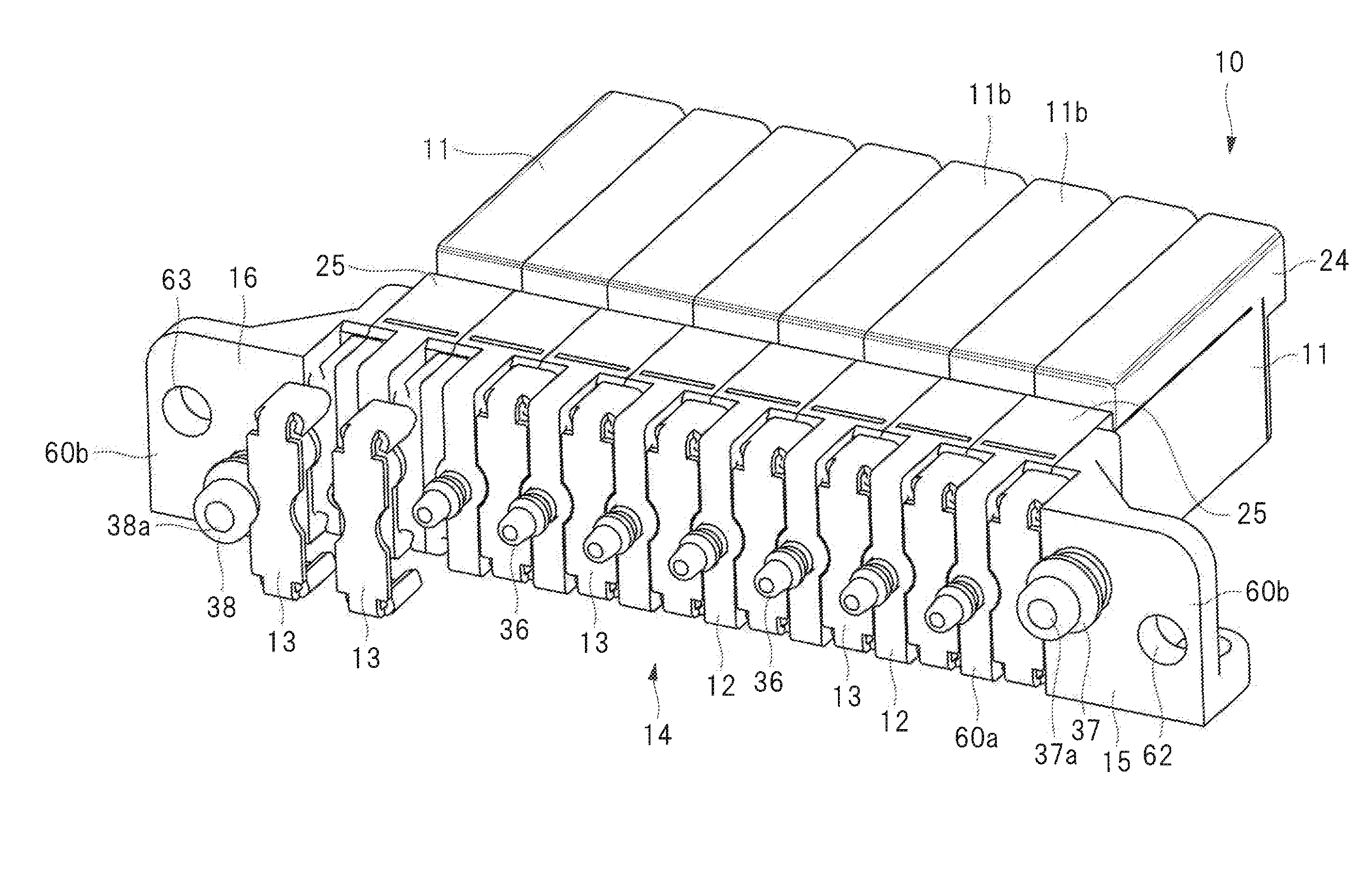
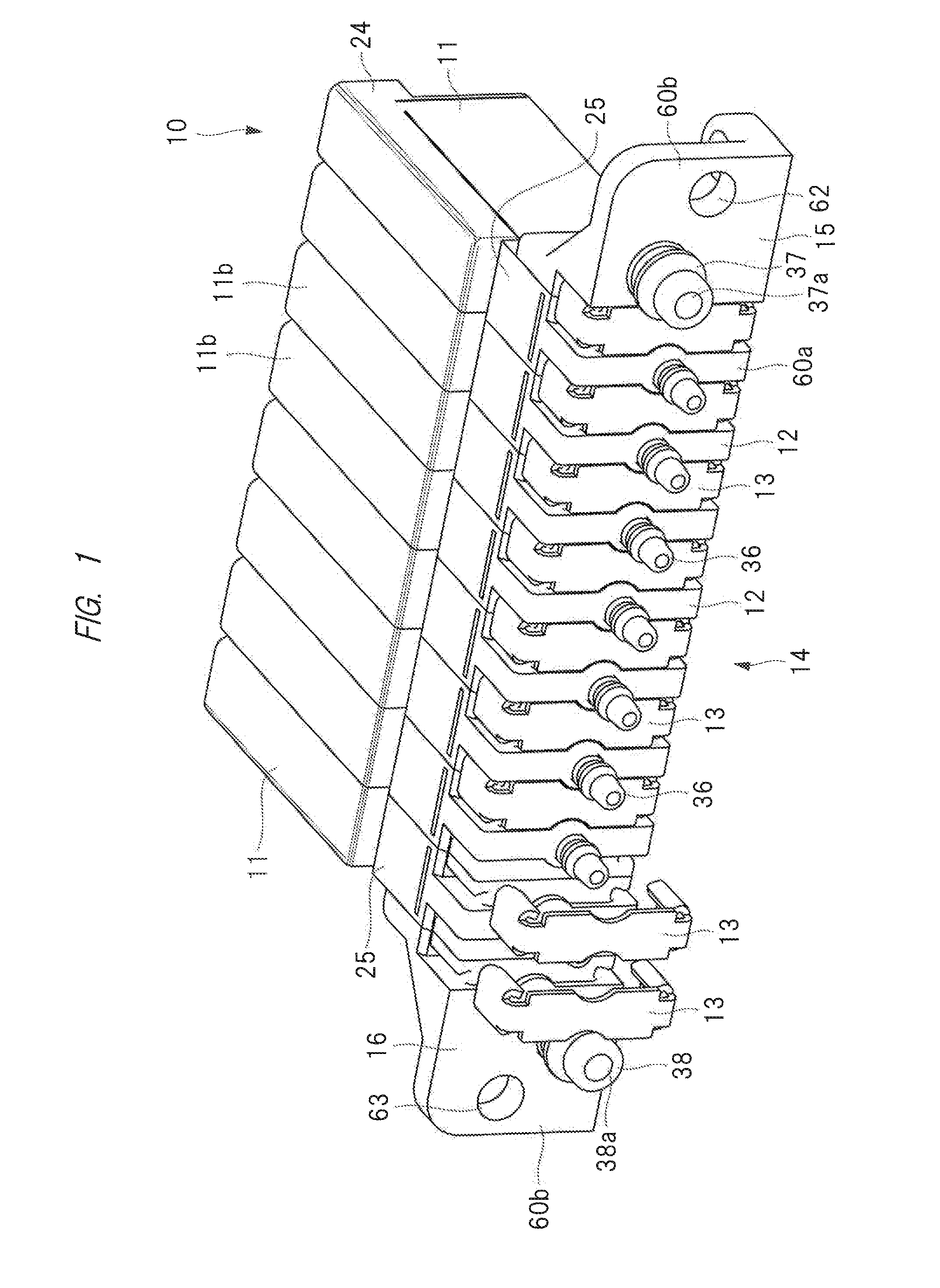
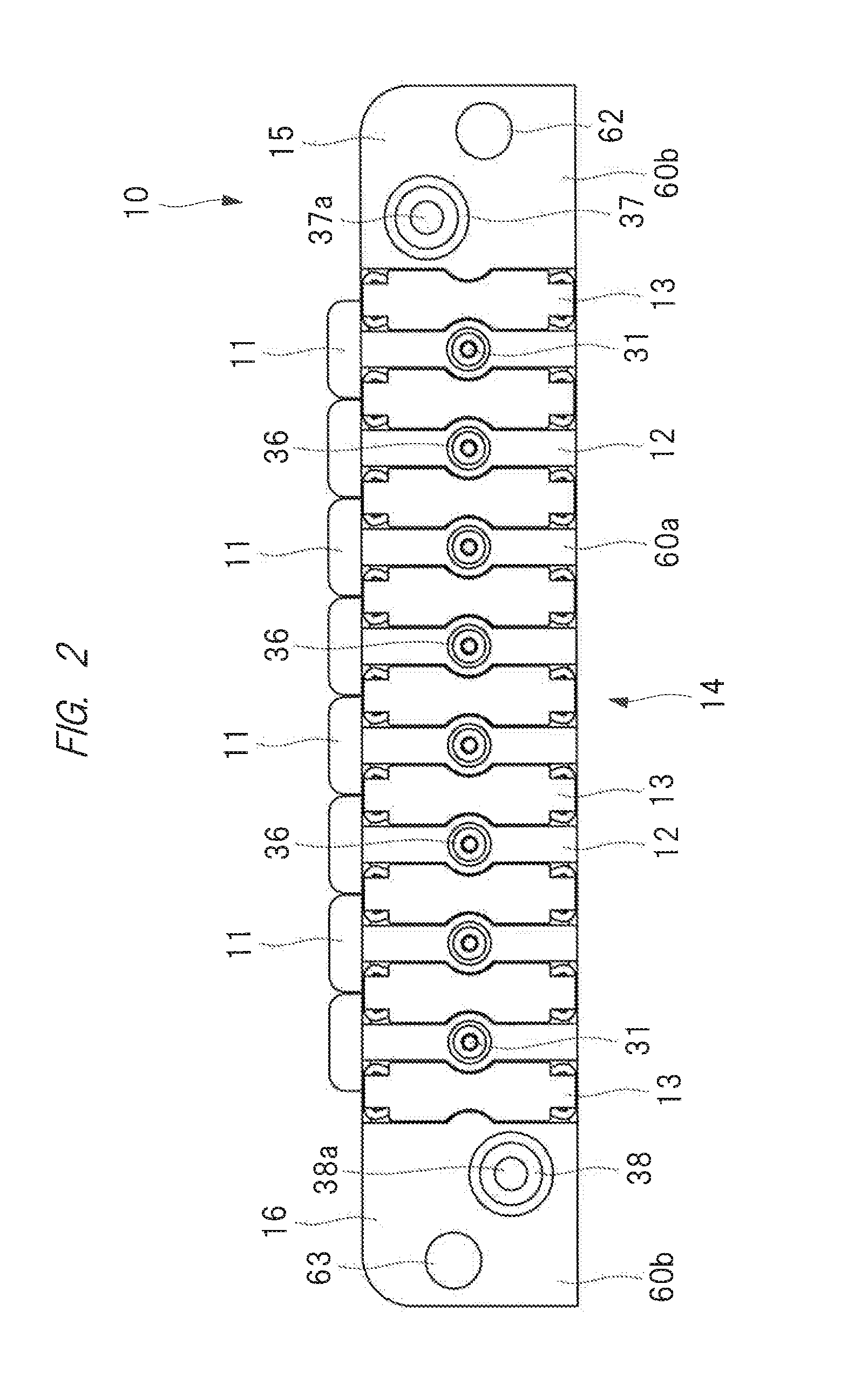
[0027]Hereinafter, an embodiment of the present invention will be described in detail on the basis of the attached drawings. As shown in FIGS. 1 to 3, a manifold solenoid valve 10 has two or more solenoid valves 11, and each solenoid valve 11 is mounted on a back face of a valve base 12 as a manifold block. The solenoid valves 11 are mounted on the respective valve bases 12, and the manifold solenoid valve 10 is a stacking type which is composed of aggregation of two or more solenoid valves 11. The manifold solenoid valve 10 is assembled so that the valve bases 12 are arranged side-by-side, and valve bases adjacent to each other abut on each other via their side faces. Although the manifold solenoid valve 10 has eight solenoid valves 11 in this embodiment, the manifold solenoid valve 10 having any number of solenoid valves 11 can be assembled by aggregating two or more solenoid valves 11.

[0028]Two valve bases 12 are adjacent to each other and arranged so as to abut on each other via...


PUM


Abstract

An object of the present invention is to improve assembling workability of the flow passage block and the sealability between the manifold solenoid valve and the flow passage block. A flow passage block 61 is mounted on a manifold solenoid valve having valve bases 12 on which solenoid valves 11 are respectively mounted, a block mounting face 60 is formed by the valve bases 12, an output joint 36 protrudes from each valve base, a joint seal member 71 is detachably mounted on the output joint 36, with the flow passage block 61 being mounted on the block mounting face 60, the joint seal member 71 seals between an outer peripheral surface of an output joint 36 and an inner peripheral surface of an connecting hole 64 which communicates with an air passage of the flow passage block 61.

Description

CROSS-REFERENCE TO RELATED APPLICATION[0001]The present application claims priority from Japanese Patent Application No. 2014-065097 filed on Mar. 27 2014, the content of which is hereby incorporated by reference into this application.TECHNICAL FIELD OF THE INVENTION[0002]The present invention relates to a manifold solenoid valve provided with a plurality of solenoid valves.BACKGROUND OF THE INVENTION[0003]Conventionally, a solenoid valve is used for controlling supply and supply stop of compressed air for a pneumatic apparatus such as a pneumatic cylinder, and for controlling a pneumatic circuit for selecting and switching pneumatic circuits. An apparatus composed as an aggregation of two or more solenoid valves is referred to as “manifold solenoid valve”. There are two different types including “integrated type” and “stacking type” in this manifold solenoid valve. In the integrated type, an aggregation of two or more solenoid valves is carried out by mounting two or more solenoid ...

Claims


Application Information

Patent Timeline
IPC IPC(8): F16K27/00F16K31/06
CPCF16K31/0675F16K27/003F15B13/0821F15B13/0839Y10T137/87885
Inventor INABA, JOJI
Owner KOGANEI
Learn More