Structural weak spot analysis

Active Publication Date: 2015-10-01
NEW YORK UNIVERSITY
View PDF17 Cites 22 Cited by
  • Summary
  • Abstract
  • Description
  • Claims
  • Application Information

AI Technical Summary

Benefits of technology

[0023]In yet another embodiment of the invention, a method and system has been developed that identifies structural problems in objects designed for 3D printing based on geometry and material properties only, without specific assumptions on loads and manual load setup. The problem is formulated as a constrained optimization problem to determine the “worst” load distribution for a shape that will cause high local stress or large deformations. While in its

Problems solved by technology

Computing multiple modes can be costly (although i

Method used


Image

  • Structural weak spot analysis
  • Structural weak spot analysis
  • Structural weak spot analysis

Examples


first embodiment

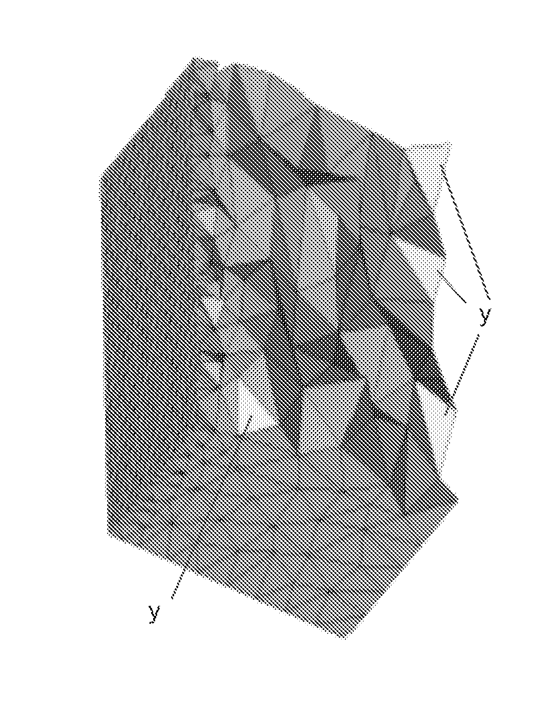
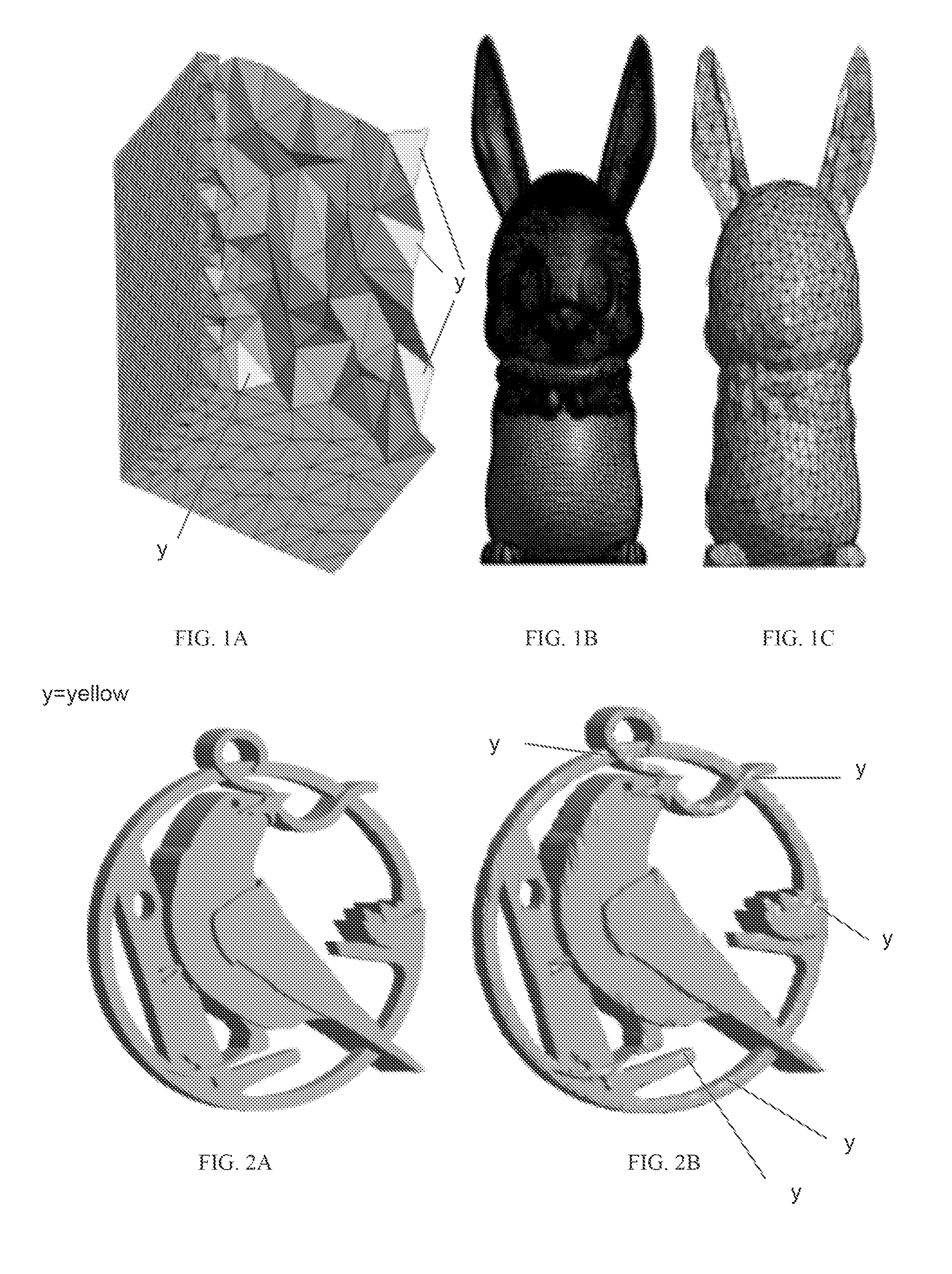
[0060]In one most preferred embodiment of this first embodiment, the methodology applies a preprocessing step to produce a tetrahedron mesh (called a “tet” mesh in the rest of this document). The starting point for tet mesh generation, for which a variety of techniques and software are available, is a triangle mesh bounding a region of spacec, which can be easily obtained from most common shape representations. Most tet mesh generation techniques add vertices in the interior of the triangle mesh and construct tetrahedra connecting these vertices. As many additional vertices may be needed in the interior to maintain good tet mesh quality, for large input triangle meshes the process may result in very large tet meshes. To keep the time and memory requirements of modal analysis and force optimization within a reasonable range, the triangle mesh may be simplified before the tet mesh is generated, using one of many available feature-preserving mesh simplification methods. (see FIG. 1A).

[...

second embodiment

[0074]In the invention, in order to carry out the worst-case structural analysis, a formal description of the problem includes a computationally intractable formulation, but it is needed as a foundation for a practical and advantageous approximate version described hereinafter.

[0075]An anisotropic linear material model is used and the linear elasticity equations applied to model object behavior for the purposes of determining weak spots and worst-case force distribution. This model is adequate for some materials used in 3D printing, but nonlinear models may be necessary for others, as discussed in greater detail hereinafter. A distinction is emphasized that should be made between simulation with given loads used to determine precise stress distributions and computation used to determine approximate worst-case loads: lower accuracy is acceptable for the latter. The standard elasticity is included to introduce notation.

[0076]The stress-strain relationship is linear, and stress is rela...


PUM


Abstract

A system and methods for weak spot analysis. A mesh shape is preprocessed to approximate an input model for an object. The mesh shape is analyzed with modal analysis to identify weak regions. A method and system for determining weak spots in an object. The method and system uses an optimization problem which is solved to determine a pressure distribution on the object maximizing maximal principal stress by solving a set of optimization problems maximizing stress for each point of the object.

Description

CROSS-REFERENCE TO RELATED APPLICATIONS[0001]This application claims the priority to U.S. Provisional Application No. 61 / 855,989, filed May 29, 2013, and U.S. Provisional Patent Application No. 61 / 718,129, filed Oct. 24, 2012. The entire contents of both applications are hereby incorporated by reference in their entirety.STATEMENT OF GOVERNMENTAL INTERESTS[0002]The United States Government claims certain rights in the invention pursuant to NSF Grant U.S. Pat. No. 0,905,502.FIELD OF THE INVENTION[0003]This invention is directed to a method and system for weak spot and also structural analysis of a shape or object. More particularly, the invention is directed to a method and system for use in commercial applications wherein mechanical stresses and strains can lead to endurance limit problems and system failure for a selected shape (object) and / or a material, such as for printing processes or any cyclic process that creates a work piece subject to mechanical forces. Further, the invent...

Claims


Application Information

Patent Timeline
IPC IPC(8): G06F17/50
CPCG06F17/5018G06F30/23
Inventor ZHOU, QINGNANZORIN, DENISPANETTA, JULIAN
Owner NEW YORK UNIVERSITY
Why Eureka
Try Eureka