Method and device for detecting a position of a vehicle on a lane

a technology for detecting the position of a vehicle and a lane, which is applied in the direction of traffic control systems, instruments, transportation and packaging, etc., can solve the problems of affecting the detection accuracy of vehicles

Active Publication Date: 2015-10-01
ROBERT BOSCH GMBH
View PDF4 Cites 13 Cited by
  • Summary
  • Abstract
  • Description
  • Claims
  • Application Information

AI Technical Summary

Benefits of technology

[0031]Due to the camera arrangement including one or multiple cameras oriented toward the side, a better color classification of lane markings or the edge of greenery is also enabled, since the side view cameras may be oriented orthogonally to the boundary almost to the greatest possible extent within a tolerance range, and are thus able to show them on many more pixels than the front view camera. Snow situations may also be detected very well. Wh

Problems solved by technology

The series systems are characterized by high availability, but their availability may decrease in difficult situations such as backlighting, night, wetness, snow or also roadworks.
The decrease in availability due to interference in the optical path and reflections on the road may also occur in stereo cameras, since there is a large, overlapping image section, and the effects occur in both camera images.
One additional aspect lies in that a robust detection of the edge of the roadway is difficult to carry out when the lane is not bounded by markings but, for example, by a median strip or guard rails.
Previous systems may lead to a driver, who has become used to the s

Method used


Image

  • Method and device for detecting a position of a vehicle on a lane
  • Method and device for detecting a position of a vehicle on a lane
  • Method and device for detecting a position of a vehicle on a lane

Examples


Embodiment Construction

[0037]In the following description of exemplary embodiments of the present invention the same or similar reference numerals are used for similar elements in the different figures, a repeated description of those elements being omitted.

[0038]The following exemplary embodiments according to the present invention show a highly available lane detection system and a lane keeping system based on front view and side view camera systems.

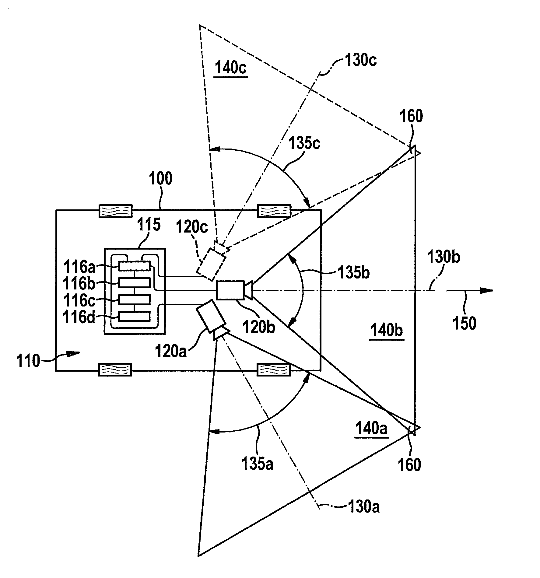
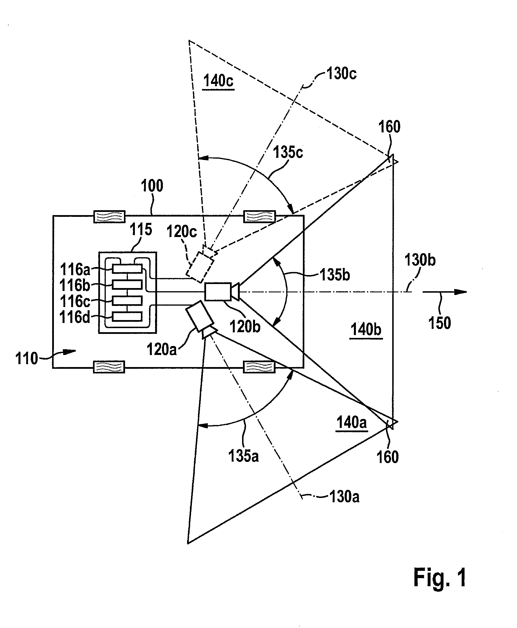
[0039]In the approach presented here, a lane detection system is presented, which estimates a lane boundary model from the three images of the camera systems used. The exemplary embodiment of the algorithm presented here is characterized in that it is highly available due to the arrangement of the cameras and the complete estimate of the lane boundary model in the three camera images, and that it enables a lane keeping function even in situations such as backlighting, bad weather, poor roads, rainbands, roadworks, grass edges, snow, etc.

[0040]FIG. 1 shows a ...


PUM


Abstract

A method for detecting a vehicle position on a lane, including: reading in a first image of a first camera, having a first optical axis and reading in at least a second image of at least a second camera having a second optical axis, the cameras being oriented so that the first and second optical axis intersect outside of the detection angle of the first and/or second camera, the first and the at least second image each enclosing a viewing angle deviating by an angle of 90 degrees maximum from the driving direction. Determining at least one interlinked image gradient for each of the first image and the at least second image. Assigning the at least one interlinked image gradient to a boundary object and assigning the at least one additional interlinked image gradient to a boundary object and/or to one additional boundary object, and ascertaining a relative position of the vehicle as to the boundary object and/or to the additional boundary object to detect the vehicle position.

Description

FIELD OF THE INVENTION[0001]The present invention relates to a method for detecting a position of a vehicle on a lane, to a corresponding device, a lane detection system and a corresponding computer program product.BACKGROUND INFORMATION[0002]Systems for detecting roadway markings (white / yellow) are nowadays based on mono or stereo cameras. The same applies to a steering assistance for the driver (lane keeping systems) based thereon. The vehicle is kept within the detected lane using a torque at the steering wheel. The series systems are characterized by high availability, but their availability may decrease in difficult situations such as backlighting, night, wetness, snow or also roadworks. The decrease in availability due to interference in the optical path and reflections on the road may also occur in stereo cameras, since there is a large, overlapping image section, and the effects occur in both camera images. One additional aspect lies in that a robust detection of the edge of...

Claims


Application Information

Patent Timeline
IPC IPC(8): G06K9/00G08G1/16G06V10/10G06V10/147
CPCG08G1/167G06K9/00791G06V20/588G06V10/16G06V10/10G06V10/147G06V20/56
Inventor RENNER, CHRISTIANHAHN, MARKUS
Owner ROBERT BOSCH GMBH
Why Eureka
Try Eureka