Positioning system for an electromechanical actuator

a technology of electromechanical actuators and positioning systems, applied in the direction of magnetic bodies, movable winding electromagnets, electric armatures, etc., can solve problems such as failure of wing functions to be appropriately positioned

Active Publication Date: 2015-10-01
THE BOEING CO
View PDF21 Cites 15 Cited by
  • Summary
  • Abstract
  • Description
  • Claims
  • Application Information

AI Technical Summary

Benefits of technology

[0018]According to various examples, a mechanism includes a flight control computer system, a translating shaft having an axis, an electromechanical actuator that moves the translating shaft along the axis, and a shaft positioning system. The electromechanical actuator is communicatively coupled to the flight control computer. The shaft positioning system includes a shaft coupled to the electromechanical actuator. The shaft moves along a linear axis and the electromechanical actuator is free to translate during normal operation. The shaft positioning sys

Problems solved by technology

If the control surface is not damped or locked, the surface can become unstable, resulting in failure of the wing to function appropriately.
However, during a power

Method used


Image

  • Positioning system for an electromechanical actuator
  • Positioning system for an electromechanical actuator
  • Positioning system for an electromechanical actuator

Examples


Embodiment Construction

[0039]In the following description, numerous specific details are set forth in order to provide a thorough understanding of the presented concepts. The presented concepts may be practiced without some or all of these specific details. In other instances, well known process operations have not been described in detail so as to not unnecessarily obscure the described concepts. While some concepts will be described in conjunction with the specific embodiments, it will be understood that these embodiments are not intended to be limiting.

INTRODUCTION

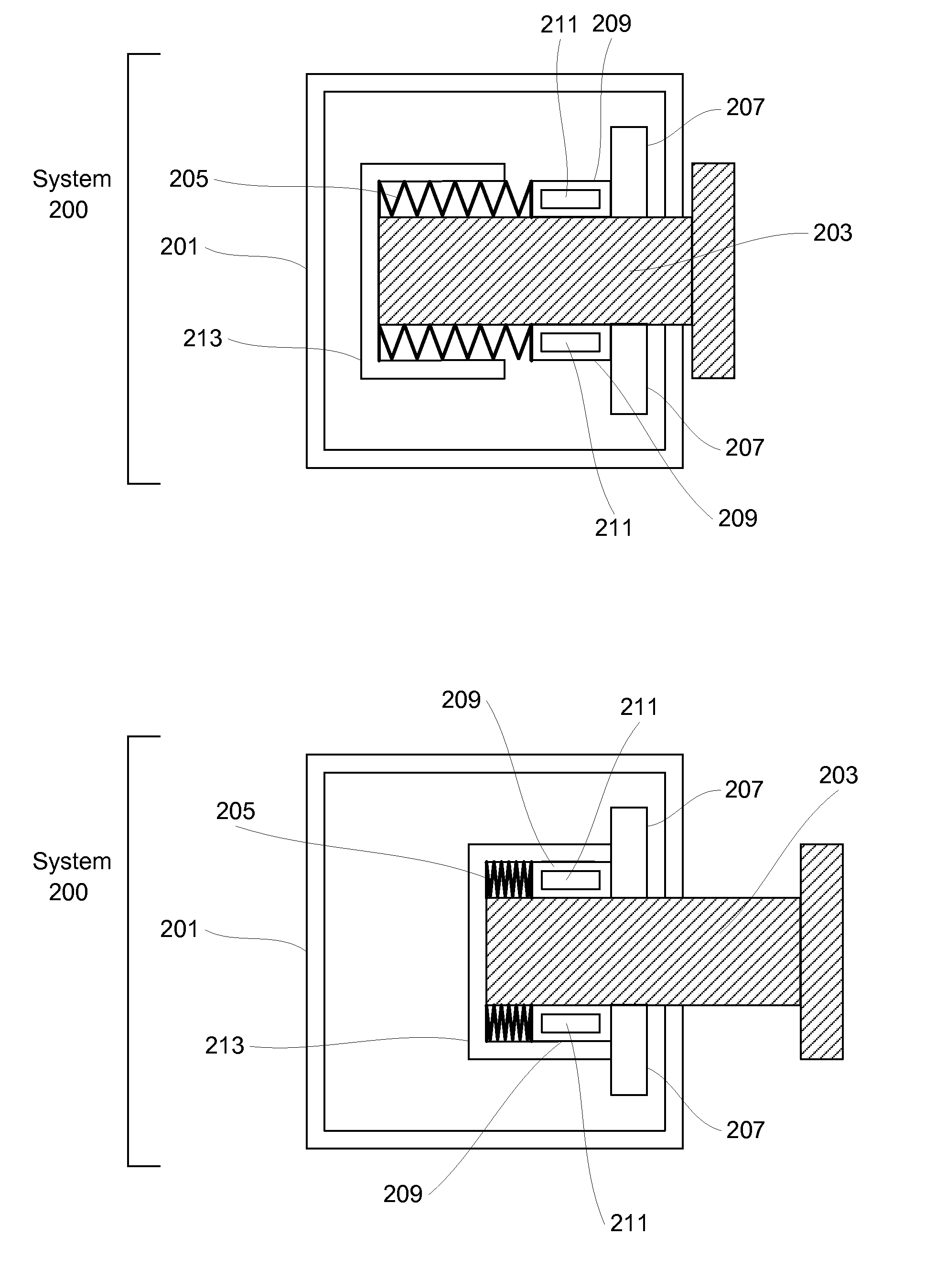
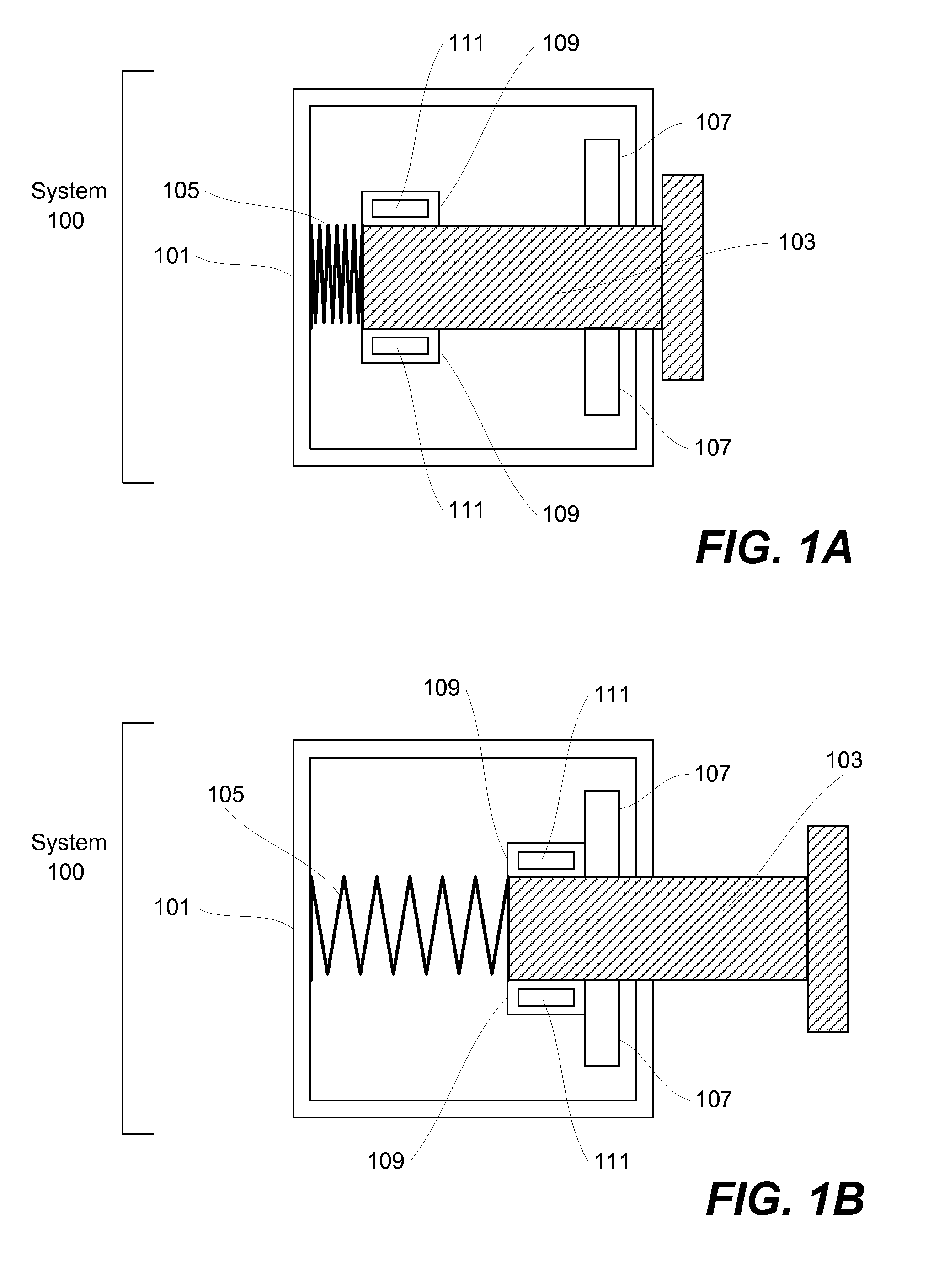
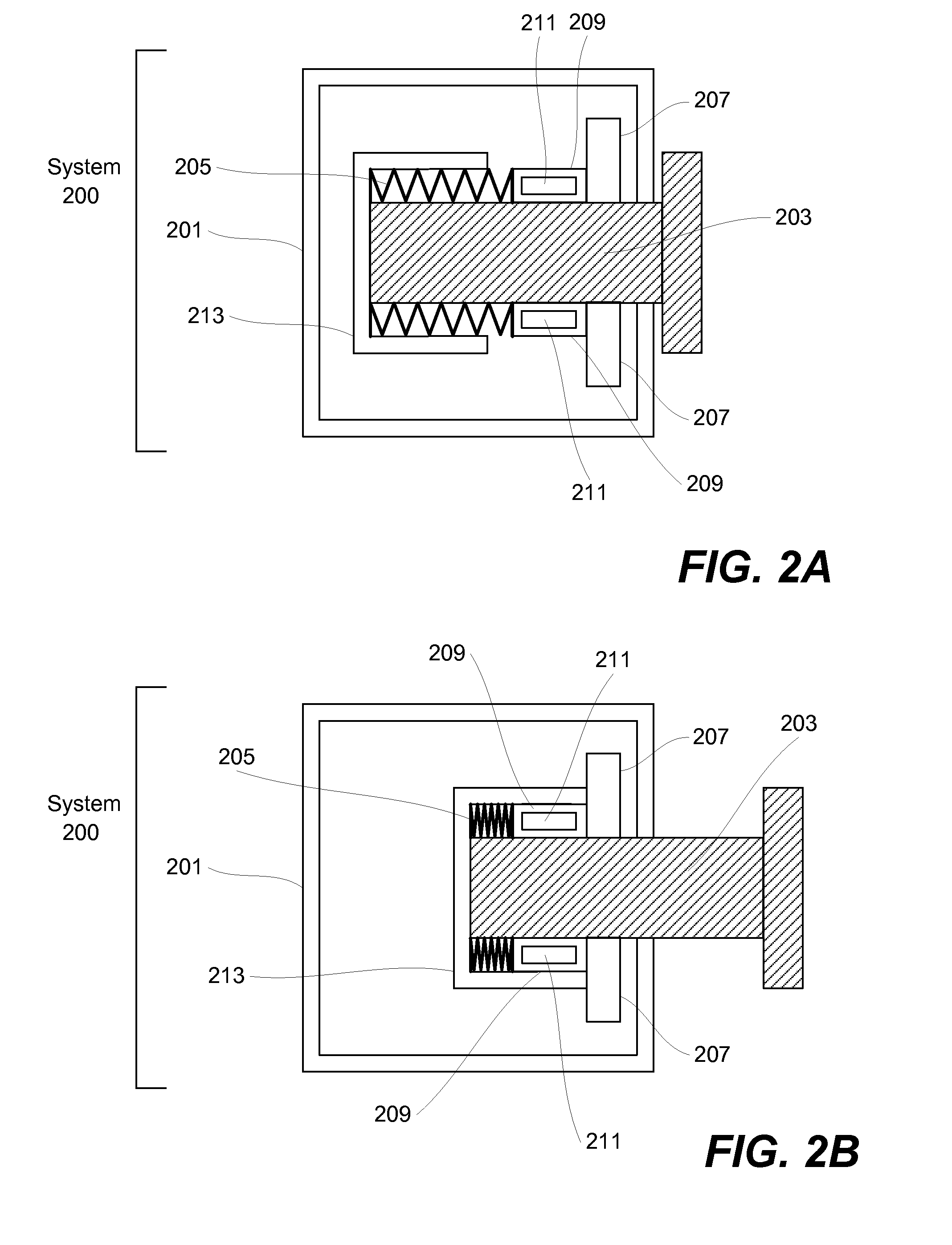
[0040]As electromechanical actuator systems are increasingly used in aircraft designs, new approaches are needed to address possible failure modes of these systems. Fault-tolerance, i.e., the ability to sustain one or more component failures or faults yet keep working, is needed in these systems. Because electric flight control systems do not have hydraulic fluid available for damping, there is a need for alternative fail safe systems that ca...


PUM


Abstract

Provided is a shaft positioning system for an electromechanical actuator. According to various examples, the positioning system includes a shaft coupled to an electromechanical actuator. The shaft moves along a linear axis and the electromechanical actuator is free to translate during normal operation. An electromagnetic coil positioned around at least a portion of the shaft. The electromagnetic coil produces a magnetic field when electrical current is applied. A metal housing surrounds at least a portion of the electromagnetic coil. The shaft is placed in a predetermined position when the metal housing is in contact with a first magnet and translational motion of the electromechanical actuator is restricted when the shaft is placed in the predetermined position.

Description

BACKGROUND[0001]Actuators are used in various mechanical devices to control the features and moving parts of these devices. Specifically, an actuator is a motor that is used to control a system, mechanism, device, structure, or the like. Actuators can be powered by various energy sources and can convert a chosen energy source into motion.[0002]For instance, actuators are used in computer disk drives to control the location of the read / write head by which data is stored on and read from the disk. In addition, actuators are used in robots, i.e., in automated factories to assemble products. Actuators also operate brakes on vehicles, open and close doors, raise and lower railroad gates, and perform numerous other tasks of everyday life. Accordingly, actuators have wide ranging uses.[0003]In the field of aeronautics, actuators are used to control a myriad of control surfaces that allow aircraft to fly. For instance, each of the flaps, spoilers, and ailerons located in each wing, require ...

Claims


Application Information

Patent Timeline
IPC IPC(8): H01F7/16H01F7/17
CPCH01F7/17H01F7/16H01F7/066H01F7/088H01F7/122H01F7/123H01F7/1615
Inventor BLANDING, DAVID E.WIJAYA, SUZANNASINGH, NIHARIKA
Owner THE BOEING CO
Why Eureka
Try Eureka