Energy storage apparatus

a technology of energy storage and energy storage device, which is applied in the direction of vent arrangement, cell components, batteries, etc., can solve the problems of adverse effects of energy storage device arranged adjacent to the overheated energy storage device, deformation of the portion of the spacer other than the projecting portion having a low melting point, and so as to prevent the thermal deformation of the projecting portion, high melting point, and low melting point

Active Publication Date: 2015-10-01
GS YUASA INT LTD
View PDF4 Cites 34 Cited by
  • Summary
  • Abstract
  • Description
  • Claims
  • Application Information

AI Technical Summary

Benefits of technology

[0007]That is, in the above-mentioned conventional configuration, it may be possible to prevent the thermal deformation of the projecting portion made of the material having a high melting point which faces the energy storage device. However, a portion of the spacer other than the projecting portion having a low melting point may be deformed due to heat generated by the energy storage device when the energy storage device is overheated. In this case, the spacer which is deformed due to heat generated by the energy storage device may be inclined between the energy storage devices so that the whole shape of the energy storage apparatus may collapse, and thus an energy storage device arranged adjacent to the overheated energy storage device may be adversely affected.
[0008]An object of the present invention to provide an energy storage apparatus which can prevent the deformation of the whole shape of an energy storage apparatus even when an energy storage device is overheated.

Problems solved by technology

Thus, an energy storage device arranged adjacent to the overheated energy storage device may be adversely affected.
However, a portion of the spacer other than the projecting portion having a low melting point may be deformed due to heat generated by the energy storage device when the energy storage device is overheated.
In this case, the spacer which is deformed due to heat generated by the energy storage device may be inclined between the energy storage devices so that the whole shape of the energy storage apparatus may collapse, and thus an energy storage device arranged adjacent to the overheated energy storage device may be adversely affected.

Method used


Image

  • Energy storage apparatus
  • Energy storage apparatus
  • Energy storage apparatus

Examples


embodiment

[0052]Firstly, the configuration of an energy storage apparatus 1 is described.

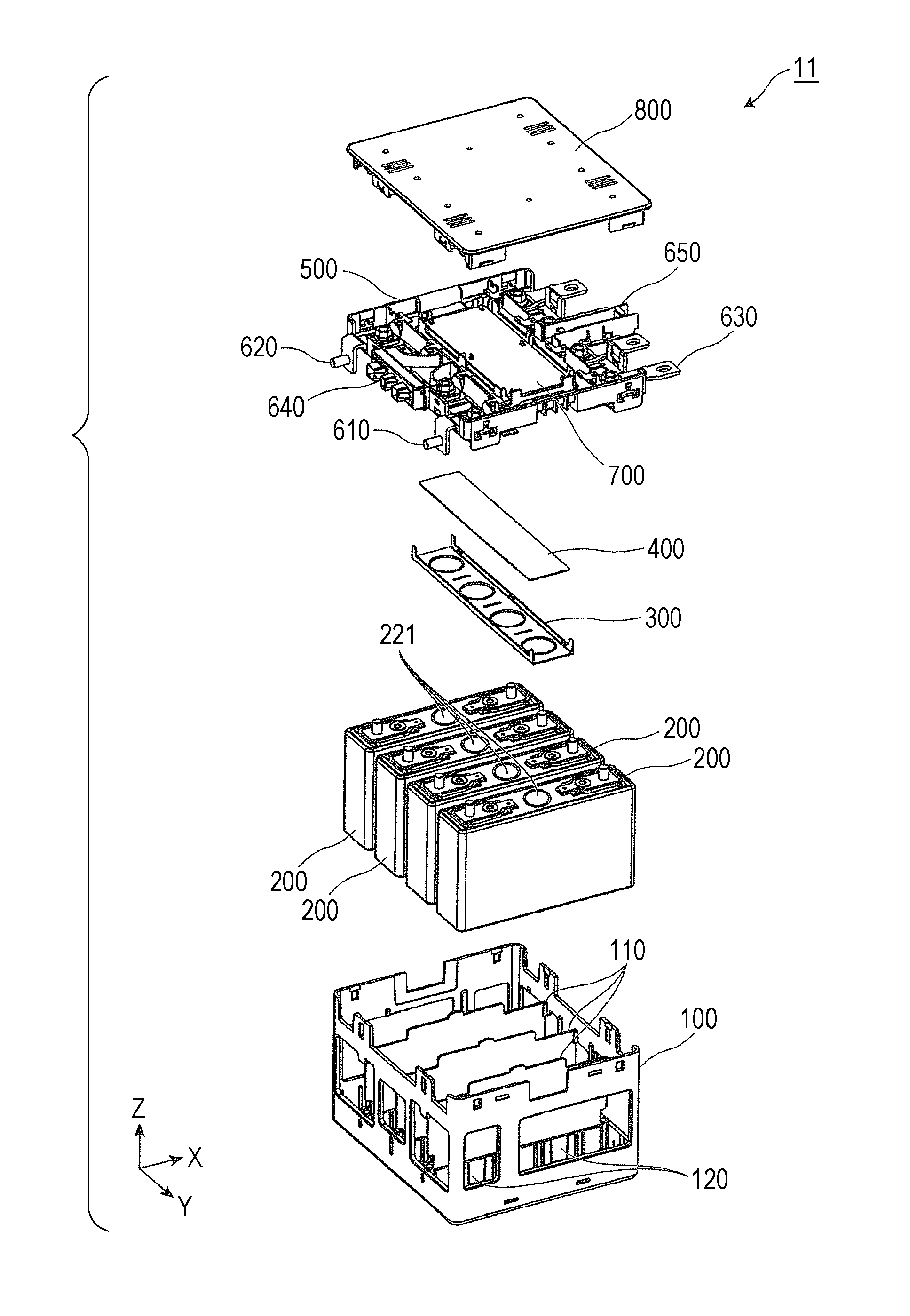
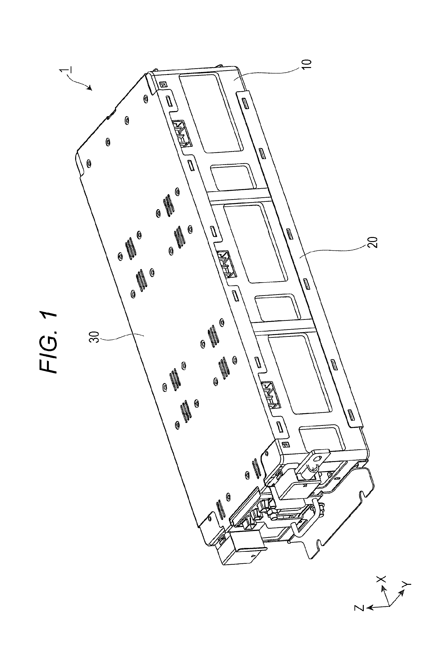
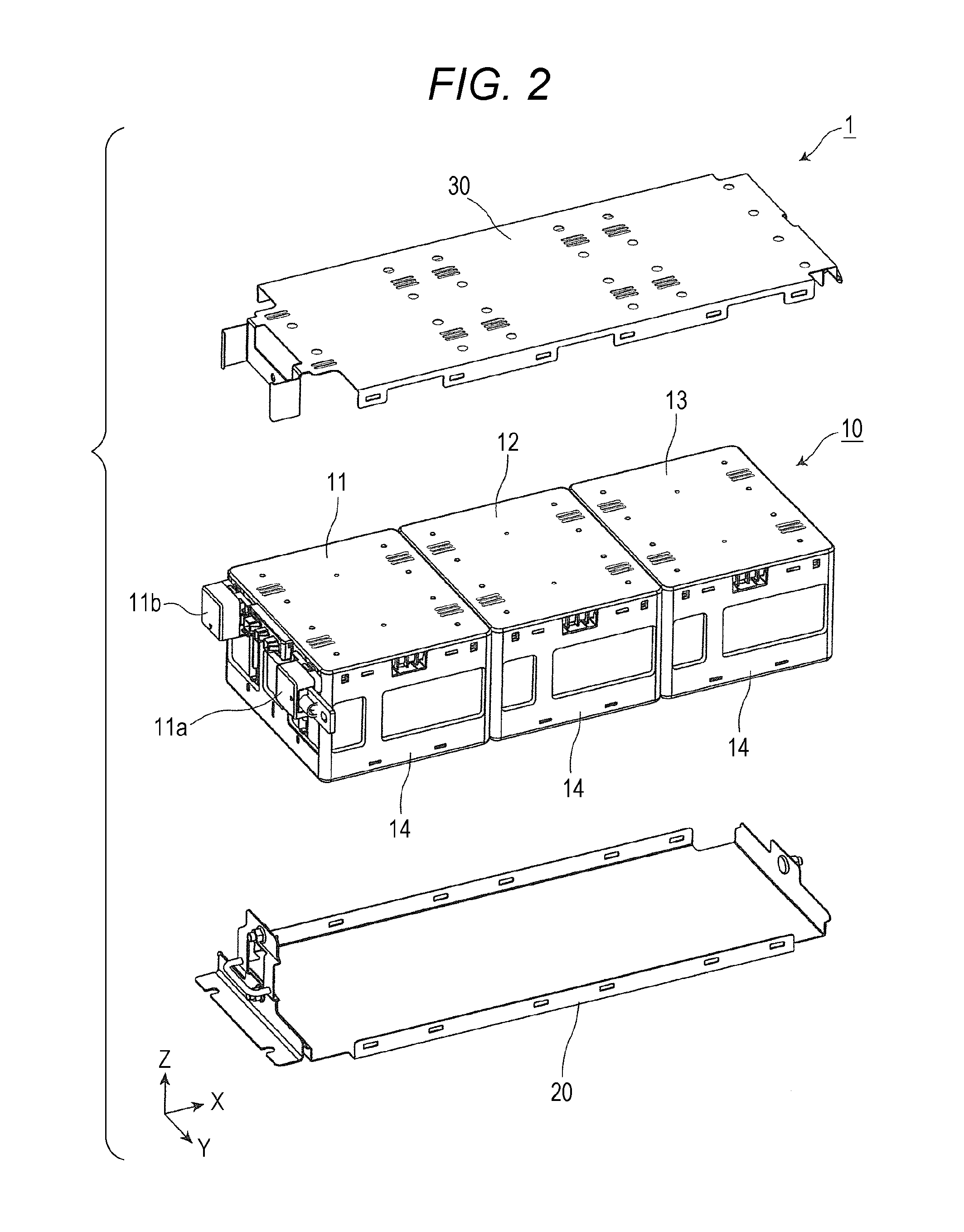
[0053]FIG. 1 shows an external appearance of the energy storage apparatus 1 according to an embodiment of the present invention in a perspective manner. FIG. 2 shows components of the energy storage apparatus 1 according to the embodiment of the present invention in an exploded and perspective manner.

[0054]In these figures, the Z axis direction is indicated as the vertical direction, and the description is made hereinafter using the Z axis direction as the vertical direction. However, there may be also a case where the Z axis direction does not indicate the vertical direction depending on a use mode and hence, the Z axis direction is not limited to the vertical direction. The same goes for drawings described hereinafter.

[0055]The energy storage apparatus 1 is a device which can be charged with electricity from the outside or can discharge electricity to the outside. For example, the energy storage apparat...


PUM

PropertyMeasurementUnit
heat resistantaaaaaaaaaa
heat resistanceaaaaaaaaaa
movementaaaaaaaaaa

Abstract

An energy storage apparatus includes: one or more energy storage devices; an outer covering arranged outside the one or more energy storage devices; a partition member arranged on a side of any one of the one or more energy storage devices; and a supporter which supports the partition member at a predetermined position. The supporter is formed of a heat resistant member.

Description

CROSS-REFERENCE TO RELATED APPLICATIONS[0001]This application claims the benefit of Japanese patent application No. 2014-073394, filed on Mar. 31, 2014, which is incorporated by reference.FIELD[0002]The present invention relates to an energy storage apparatus which includes one or more energy storage devices and an outer covering arranged outside such one or more energy storage devices.BACKGROUND[0003]Concerning an energy storage apparatus in which energy storage devices are housed in an outer covering, there has been known the configuration, where a spacer (a partition member) is disposed between the energy storage devices. The spacer is generally made of a resin and hence, when the energy storage device arranged adjacent to the spacer is overheated to a high temperature, there is a possibility that the spacer is deformed due to heat.[0004]Conventionally, there has been proposed an energy storage apparatus where the deformation of the spacer due to heat generated by the energy stor...

Claims


Application Information

Patent Timeline
Patent Type & Authority Applications(United States)
IPC IPC(8): H01M2/16H01G9/08H01G9/15H01M2/12H01M2/02H01M50/209H01M50/227H01M50/244H01M50/262H01M50/271H01M50/284
CPCH01M2/16H01M2/12H01M2200/20H01G9/15H01G9/08H01M2/02H01M10/4257H01M10/658Y02E60/10H01M50/209H01M50/383H01M50/394H01M50/581H01M50/284H01M50/227H01M50/244H01M50/271H01M50/262
Inventor OHSHIBA, MASASHIKOYAMA, HIROYASUFUJISAWA, KAZUYAMIZUKAWA, YUTA
Owner GS YUASA INT LTD
Why Eureka
Try Eureka